
Lifting and rigging OPERATIONS Instructor Andy Bruce


loler._rigger_banksman_slides.ppt
- Размер: 14.6 Mегабайта
- Количество слайдов: 109
Описание презентации Lifting and rigging OPERATIONS Instructor Andy Bruce по слайдам
Lifting and rigging OPERATIONS
Instructor Andy Bruce
AIMS AND OBJECTIVES Target Audience : — This 3 day course is intended for all categories of personnel involved in slinging and lifting operations. To ensure delegates have an understanding of the legal requirements pertaining to hoisting and lifting operations, the practical ability and skills necessary to direct crane operations using both British standard hand signals and radio communications, the requirements for pre-use inspection and discard criteria of lifting equipment, the safe working procedures for slinging operations and to ensure delegates can use lifting equipment safely and effectively. AIMS : —
Content: — Legislation Regulations H S E Guidance Basic Crane Appreciation Pre- use examination of lifting equipment Inspection of lifting equipment Slinging of various loads. Safe operating procedures Weight estimation Load stability. Wire rope safety, inspection and care Safe slinging principles. British standard hand signals Radio communication
L O L E R Reg`s Cont`d 6. Every employer shall reduce to as low as possible. • The load from striking people. • Load drifting. • Falling. • Being released unintentionally. 7. Every employer shall ensure that I. e. equipment for lifting people is clearly marked. 8. Properly planned Properly supervised Carried out in a safe manner
L O L E R Loler regulations 1. Came into effect 5 th Dec 1998. From this date holders must comply with all the all duty requirements. 5. Lifting equipment for lifting persons. 2. Defining the terms etc. I E. 1974 act means the Health and safety at work act 1974. 3. To whom and where. • Ships Merchant Shipping. • Slips Trips And Falls. • Risk Assessment. 4. Calls upon the employer to ensure that the strength and stability are adequate.
L O L E R Reg`s Cont`d 11. Keeping of information. 9. Thorough examination and inspection. • Lifting persons every 6 months. • Accessories lifting gear slings hooks shackles 6 months. • Lifting equipment, mechanical device capable of raising or lowering a load 12 months. 10. Report and defects.
LIFTING OPERATIONS APPLICABLE LEGISLATION • HEALTH & SAFETY AT WORK etc 1974. • MANAGEMENT OF HEALTH&SAFETY AT WORK REGULATIONS 1992. • LIFTING OPERATIONS AND LIFTING EQUIPMENT REGULATIONS 1998. • PROVISION AND USE OF WORK EQUIPMENT REGULATIONS 1992 (AMENDED 1998). • MANUAL HANDLING OPERATIONS REGULATIONS 1992.
LIFTING OPERATIONS APPLICABLE LEGISLATION HEALTH & SAFETY AT WORK etc ACT 1974 • EMPLOYERS RESPONSIBILITIES — It shall be the duty of every employer to ensure, as far as is reasonably practicable, the health, safety and welfare at work of all his employees. • EMPLOYEES RESPONSIBILITIES — To take reasonable care for the health and safety of themselves and others who may be affected by their acts or omissions. — They must co-operate with their employers as far as is necessary to enable that duty or requirement to be performed or complied with. — No person shall intentionally or recklessly interfere with or misuse any equipment provided in the interest of health, safety or welfare.
3 LIFTING OPERATIONS APPLICABLE LEGISLATION Management Of Health & Safety At Work Regs 1992 • Requires employers and self employed persons to assess the risks to workers and any others who may be affected by their undertaking • Employers with five or more employees must also record the significant findings of that assessment • Assessment should be reviewed and if necessary modified when the nature of the work or the physical conditions of the work place changes. • Suitable and sufficient risk assessments should — — be carried out by a competent person — ensure that all relevant risks or hazards are addressed — determine the likelihood of injury or harm arising — take into account any existing control measures.
LIFTING OPERATIONS APPLICABLE LEGISLATION Management Of Health & Safety At Work Regs 1992 cont`d 4 — Identify the measures that employers must take in order to comply with their duties under the applicable health and safety legislation. — Generic or “model”risk assessments are acceptable where similar activities are being under taken in similar places of work.
5 LIFTING OPERATIONS APPLICABLE LEGISLATION Provision And Use Of Work Equipment Regs 1992 • Every employer shall: — • Ensure that work equipment is so constructed or adapted as to be suitable for the purpose for which it is used or provided. • The suitability of work equipment should be addressed from three aspects. — it’s initial integrity, — the place where it will be used, — the purpose for which it will be used. • In selecting work equipment every employer shall have regard to the working conditions and to the risks to the health and safety of persons which exist in the premises or undertaking in which the work equipment is to be used.
6 LIFTING OPERATIONS APPLICABLE LEGISLATION Provision And Use Of Work Equipment Regs 1992 cont`d • “ suitable” means that it must be suitable by design, construction or adaptation for the work it is provided to do and suitable in every respect which it is reasonably foreseeable will affect the safety and health of any person. • Risk assessments carried out under the MHSWR will help employers to select work equipment and assess it’s suitability for particular tasks. Every employer shall ensure: — • That work equipment is maintained in an efficient state, in efficient working order and in good repair, and the where there is a maintenance log it is kept up to date.
7 LIFTING OPERATIONS APPLICABLE LEGISLATION • The use of work equipment is restricted to those persons given the task of using it. • That all persons who use or supervise the work equipment have available to them adequate health and safety information and where appropriate written instructions pertaining to its use. • That all persons who use work equipment have received adequate training in the methods which may be adopted when using the work equipment , any risks which are entailed and precautions to be taken • That effective measures are taken to prevent contact with dangerous parts of machinery, this includes measures at four levels-fixed enclosing guards, other guards or protection devices, protection appliances and the provision of information. Provision And Use Of Work Equipment Regs 1992 cont`d
8 LIFTING OPERATIONS APPLICABLE LEGISLATION Manual Handling Operations Regs 1992 • Manual handling operations-means any transporting or supporting of a load by hand or bodily force -I. e. lifting, pulling, pushing, carrying, putting down or moving thereof by hand or bodily force. • They refer to the manual handling of loads by human effort as opposed to mechanical handling by a crane or other such equipment. • A load in this context must be a discrete moveable object but does not include an implement, tool or machine while in use. • The reg`s seek to prevent injury to any part of the body and as such account should be taken of physical properties which may effect grip or cause direct injury. • Each employer shall so far as is reasonably practicable, avoid the need for his employee to undertake any manual handling at work.
9 LIFTING OPERATIONS APPLICABLE LEGISLATION Manual Handling Operations Regs 1992 cont`d • Where it is not reasonably practicable to avoid the need for the employee to under take manual handling which involves the risk of injury, the employer shall make a suitable and sufficient assessment of all such manual handling operations. • The assessment should be carried out by a competent person and shall take into account the task, load, and working environment. • Properly based generic assessments are acceptable if they draw together common threads from a range of broadly similar manual handling operations. • Manual handling assessment findings must be recorded.
LIFTING OPERATIONS APPLICABLE LEGISLATION 10 Lifting Operations And Lifting Equipment Regulations 1998 • Regulation. 1 — Citation and commencement-lays out scope and timing. • Regulation. 2 — Interpretation -Definitions • Regulation. 3 — Application-Details where and to whom the regulations apply. • Regulation. 4 — Strength and stability-Calls upon the employer to ensure that the strength and stability of lifting equipment is adequate for use. • Regulation. 5 — Takes precedence over all other LOLER reg`s when lifting of persons is to be carried out. • Regulation. 6 — Positioning and installation of equipment to minimise risk.
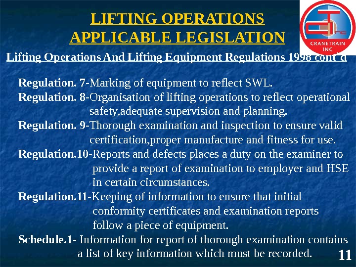
LIFTING OPERATIONS APPLICABLE LEGISLATION 11 Lifting Operations And Lifting Equipment Regulations 1998 cont`d Regulation. 7 — Marking of equipment to reflect SWL. Regulation. 8 — Organisation of lifting operations to reflect operational safety, adequate supervision and planning. Regulation. 9 — Thorough examination and inspection to ensure valid certification, proper manufacture and fitness for use. Regulation. 10 — Reports and defects places a duty on the examiner to provide a report of examination to employer and HSE in certain circumstances. Regulation. 11 — Keeping of information to ensure that initial conformity certificates and examination reports follow a piece of equipment. Schedule. 1 — Information for report of thorough examination contains a list of key information which must be recorded.
___________ TRAINING PRESENTATION
LIFT ING OPERAT IONS PLANPAGE 1 of 1 Location: Kittiw ake A lpha. A rea: Helideck to Pipe deck Permit No. : Risk A ssessment No: KWA /HLRA /002 Generic Lif ting Plan No: 02 Method Statement No. : N/A Is Diagram/Sketch Of Lif ting Operation Enclosed? Y ES/NON/A Description Of Lif ting Operation: Routine use of platf orm cranes f or transf er of cargo f rom helidec k to pipedeck Weight Of Load: A CTUA L / A SSESSED (delete as appropriate) Lif ting Equipment & A ccessories To Be Used (spec if y type, sw l & colour c ode) Pre-slung containers and cargo baskets w ith c ertif ied lif ting bridle and shackles Installation pedes tal c ranes / Crane cargo handling pendant A ll Lif ting Operations Require The Follow ing To Be Considered But This List Is Not Exhaustive. w eight, size, shape and centre of gravity of loadw orking under s uspended loads method of slinging/attaching/detaching the loadoverturning/load integrity/need f or tag lines availability of approv ed lif ting points on loadenvironmental conditions including w eather pre-use equipment c hecks by operatorexperience, competence and training of personnel prox imity hazards, obs tructions, path of loadnumber of personnel required f or tas k conf licting tasks in areac ommunication requirements Task Details (Step By Step) 1 The lif ts are c ontainers and cargo baskets w ith certif ied lif ting points, and f itted w ith a c ertif ied lif ting bridle 2 A ll personnel associated w ith lif t to review specif ic risk assess ment/lif ting f low chart and complete toolbox talk prof orma prior to c ommencing lif ting operation 3 Competent Crane Operator to carry out pre-start checks/inspec tions of Crane and record on PMR prof orma 4 Integrity of loads and assoc iated equipment to be checked by deck crew personnel 5 A minimum of 2 competent deck crew to be in attendance throughout lif ting operation (w ith V HF portable radios)6 Banks man/Crane Op to as certain environmental conditions are w ithin crane parameters 7 Under the instruc tion of the banks man position crane boom ov er load and ensure load line is plumb 8 Ensure no c onf licting activities ongoing in surrounding/landing areas and load path is c lear of obstruc tions 9 A ttatc h mas ter ring of loads lif ting bridle onto crane cargo handling pendant 10 Instruct crane operator to take up slack on lif ting arrangement and raise load f rom deck slow ly (under instruction)11 Crane op to raise load to clear any obstructions and f ollow banks man ins tructions to transf er load to landing area 12 Deck crew to ensure landing area is clear of personnel and obstac les/conf licting activ ities 13 Banks man to instruct crane operator to low er load s low ly, (ensure load line is plumb) into position on landing area 14 Cargo handler to detach lif ting bridle master ring f rom crane cargo handling pendant 15 Raise empty hook under instruction f rom banks man and return crane to stow ed pos ition Method(s) Of Communication To Be Used Radio. V erbal. Hand Signals Steps Taken To Eliminate Danger To Personnel Involved & Others, Including Barriers Where A ppropriate: V igilant observation By deck crew and crane operator. De-brief and learning points: Planned By: Name: C Milne Signature: Date: Review ed By: Name: Signature: Date: XX__________ TRAINING PRESENTATION
___________________ TRAINING PRESENTATION
___________________ TRAINING PRESENTATION
TRAINING PRESENTATION
___________________ TRAINING PRESENTATION
___________________ TRAINING PRESENTATION
___________________ TRAINING PRESENTATION
___________________ TRAINING PRESENTATION
GUIDELINES FOR SLINGER/BANKSMAN 1. Do everything possible to ensure the safety of personnel and equipment. 2. Be familiar with the crane working range, load radius and boom angle. 3. Know and understand appropriate safe slinging principles. 4. Inspect lifting accessories each time before use. 5. Know the weight of the load and the slinging methodology. 6. Be able to select the correct equipment for the job in hand. 7. Be aware of obstructions and hazards within operating range. 8. Know and understand the method of banksman hand signals. 9. Give clear and precise hand signals. 10. Use correct protocol during radio communication.
GUIDELINES FOR SLINGER/BANKSMAN 11. Warn personnel in the area of the movement of the load. 12. Never lift a load over personnel. 13. Never stand beneath a load or allow other personnel to do so. 14. Ensure hands are clear from lifting gear prior to lifting loads. 15. Always ensure an escape route is available prior to lifting loads. 16. Always use tag lines especially for awkward loads. 17. Ensure a minimum of 3 personnel is deployed for each lifting operation. I. E. Crane operator, Banksman and slinger. 18. If anything out of the ordinary occurs — STOP and CHECK. 19. Be aware of potential snagging points in the vicinity of the load whilst hoisting/lowering in restricted areas. 20. Be aware of wind speed and direction which could affect the lifting operation.
5 SIMPLE RULES FOR A BANKSMAN 1. Know the _______ of the _______. 2. ____ the right_____ for the job. 3. Attach it ______ to the load, ensuring that the hook is over the ___ of the load. 4. Before lifting ensure that ______ are clear of the slings. 5. Lift ____ and _______. Ensure all _____ are clear of the load. weightload Use. Lifting equipment correctly CG hands slowlycarefullypersonnel___________________ TRAINING PRESENTATION
CONTROLLING CRANE OPERATIONS BY TWO WAY RADIO COMMUNICATION PROTOCOL FOR THE USE OF TWO WAY RADIO COMMUNICATIONS • Call signs should be set up and adhered to. • Call signs must be used at all times in order to establish the authenticity of commands or directions. • At the end of an instruction or enquiry, the transmitting operator should indicate the end of the message by the command ‘over’. • The receiving operator should indicate understanding of the dialogue by the response “roger”. • Under no circumstances should the transmitting operator assume understanding without the acknowledgement I. E. “roger”. • If any dubiety exists regarding the message, the receiving operator must not acknowledge but repeat the message as he understands it and ask for confirmation, or simply request the transmitting operator to repeat.
CONTROLLING CRANE OPERATIONS BY TWO WAY RADIO COMMUNICATION PROTOCOL FOR THE USE OF TWO WAY RADIO COMMUNICATIONS • At the close of communications the transmitting operator should indicate the end on transmission by the command “ over and out”. • Bearing in mind the broadcasting legislation, under no circumstances should profane language be used while transmitting. • Bearing in mind that these radios are transmitting at a high output, should the antenna ever become damaged exposing the central core, the antenna must be immediately replaced in order to maintain not only optimum performance but to ensure user safety.
CONTROLLING CRANE OPERATIONS BY TWO WAY RADIO COMMUNICATION GENERAL INFORMATION ON THE USE OF TWO WAY RADIO COMMUNICATION • The Crane Operator and Banksman should establish a clear understanding and line of communication prior to the commencement of any lifting operation. Radio messages should reflect work requirements only. General conversation should not be carried out over the air waves. • Always ensure that you fully depress the transmission button before speaking into the microphone. Speak clearly at all times. Do not release the button until a few seconds after completing your message.
CONTROLLING CRANE OPERATIONS BY TWO WAY RADIO COMMUNICATION GENERAL INFORMATION ON THE USE OF TWO WAY RADIO COMMUNICATION • When banking the crane ensure that any accompanying colleagues’ radios are switched off. When more than one radio is switched on in close proximity, it is inevitable that interference and/or distortion of the signal will take place when an instruction is transmitted. • When you have established a clear line of communication with the crane operator ensure that if you move position you re-establish that he is still receiving your message clearly. • During high winds ensure that the area of the microphone you speak into is not exposed to direct contact with the wind. Otherwise the background noise created may distort the transmission.
CONTROLLING CRANE OPERATIONS BY TWO WAY RADIO COMMUNICATION GENERAL INFORMATION ON THE USE OF TWO WAY RADIO COMMUNICATION • During ‘blind’ lifts where the load is being hoisted or lowered for a long time (eg shaft/leg work) do not maintain the transmission button in the depressed position for the duration of the lift. Likewise do not give an instruction at the commencement of the lift and then cease communication until the lift has almost reached its destination. Give the initial instruction and then talk to the Crane Operator every 10 -15 ft to reassure him that your line of communication is still active and that you are maintaining control of the lift.
CONTROLLING CRANE OPERATIONS BY TWO WAY RADIO COMMUNICATION • Ensure the radio microphone is not exposed to rain. If a plastic carrying case offering full protection of the radio is not available, a simple precautionary measure such as a small plastic bag or a piece of cling film around the microphone will ensure it is maintained in a dry condition. • Do not carry radios in pockets. Always ensure they are carried in protective holsters attached to the body by either should lanyard or waist belt, quite apart from maintaining the integrity of the radio this measure will also ensure that you are not exposing other personnel to danger should the radio be dislodged from your pocket or dropped from hand when working at height or climbing ladders.
TRAINING PRESENTATIONCRANES AND BOOM TYPES CRAWLER MOUNTED LATTICE (STRUT) BOOM TRUCK MOUNTED TELESCOPIC PEDESTAL MOUNTED FIXED BOX PEDESTAL MOUNTED LATTICE (STRUT) BOOM
___________________ TRAINING PRESENTATION
STABILITY BASE CRAWLER CRANE CENTRE OF GRAVITY NO LOAD WITHOUT OUTRIGGERS WITH OUTRIGGERS ___________________
___________________ TRAINING PRESENTATIONSTABILITY SAFE LOAD — CENTRE OF GRAVITY SUPPORTED OVER LOAD — CENTRE OF GRAVITY UNSUPPORTED CRANE MUST TIP
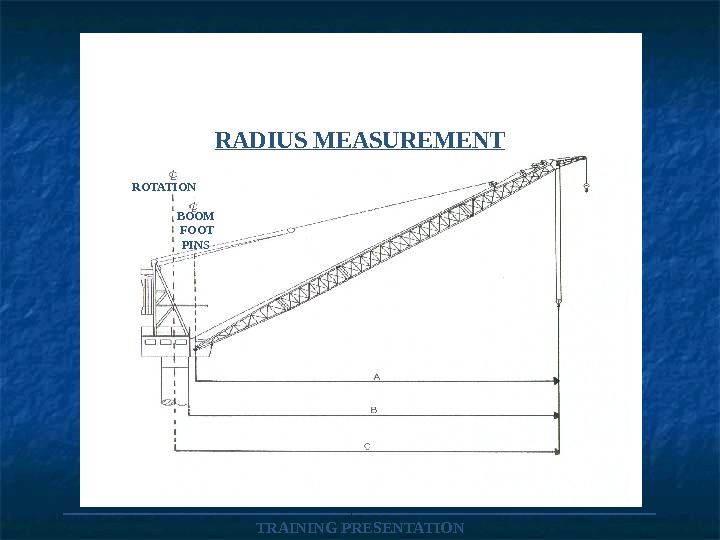
___________________ TRAINING PRESENTATIONRADIUS MEASUREMENT ROTATION BOOM FOOT PINS
Angle Boom Angle The angle from the horizontal (0°) at which the boom rests. 0 °
Boom Sections A crane boom is usually in two sections: Upper and Lower. It may be be lengthened by the insertion of one or more intermediate sections. UPPER SECTION LOWER SECTIONINTERMEDIATE’S
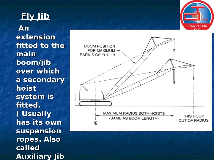
Fly Jib An An extension fitted to the main boom/jib over which a secondary hoist system is fitted. ( Usually has its own suspension ropes. Also called Auxiliary Jib
Outrigge rr Auxiliary equipment for extending the effective base of a crane to increase its stability.
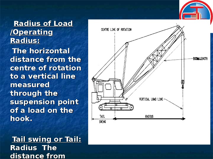
Radius of Load /Operating Radius: The horizontal distance from the centre of rotation to a vertical line measured through the suspension point of a load on the hook. Tail swing or Tail: Radius The distance from centre of rotation to furthermost point of rear of machine. RADIU S
Mobile crawler
Mobile (Truck Mounted) Telescopic. C R A N E T R A I N I N T E R N A T I O N A L
Lattice boom
Articulated (knuckle-boom)
Fixed Box
GLOBAL DYNAMICS The effect of global dynamics will be significantly influenced by parameters such as: — • The environmental conditions • Rigging arrangement • Type of crane vessel • Stiffness of crane boom and lifting appliances • Type of cargo vessel • Weight of lifted object • Lifting procedures
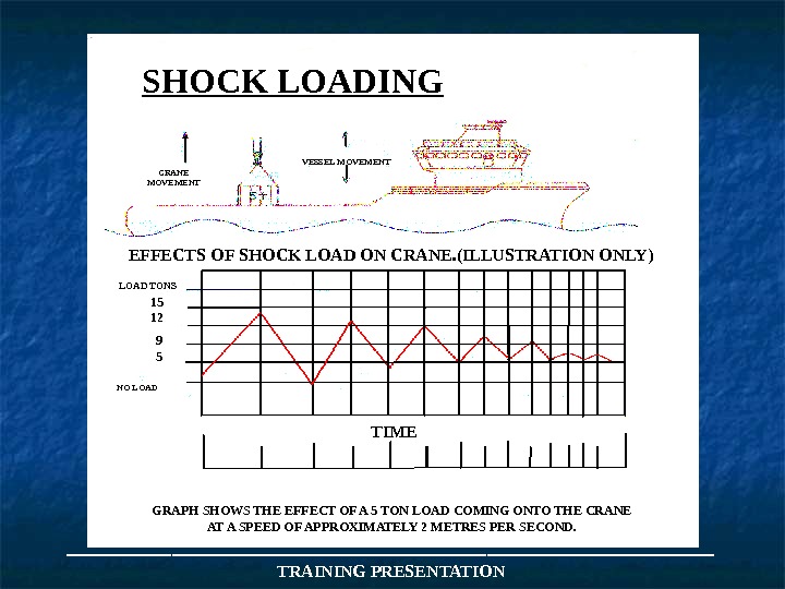
CRANE MOVEMENT VESSEL MOVEMENT NO LOAD 15 12 9 5 LOAD TONS SHOCK LOADING EFFECTS OF SHOCK LOAD ON CRANE. (ILLUSTRATION ONLY) TIME DEPENDS ON BOOM LENGTH AND ANGLE. GRAPH SHOWS THE EFFECT OF A 5 TON LOAD COMING ONTO THE CRANE AT A SPEED OF APPROXIMATELY 2 METRES PER SECOND. ___________________ TRAINING PRESENTATION
___________________ TRAINING PRESENTATIONESTIMATION OF WEIGHT
8 ft 10 ft 20 ft. WEIGHT ESTIMATION ½ THICK STEEL ½ FULL OF FRESH WATER WEIGHT OF CONTAINER WEIGHT OF WATER 20 X 8 = 160 20 X 10 = 200 10 X 8 = 80 440 X 2 (Sides) 880 ▫FT X 20 Lbs 17600 lbs Dead wt (L x B x H) 20 x 10 x 8 = 1600 ▫ft ÷ 2 = 800 ▫ft X 62 lbs = 49600 lbs 17600 lbs 67200 lbs + 25% = 16800 lbs Total Est weight: 84000 lbs # REMEMBER TO ADD 25% TO TOTAL
END OF DAY ON
WIRE ROPES
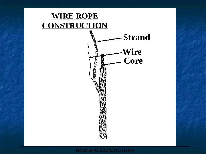
WIRE ROPE CONSTRUCTION Strand Wire Core ___________________ TRAINING PRESENTATION
Generally speaking, all ropes nowadays are PREFORMED in manufacture and there are a great many different rope constructions, each one having its own particular use.
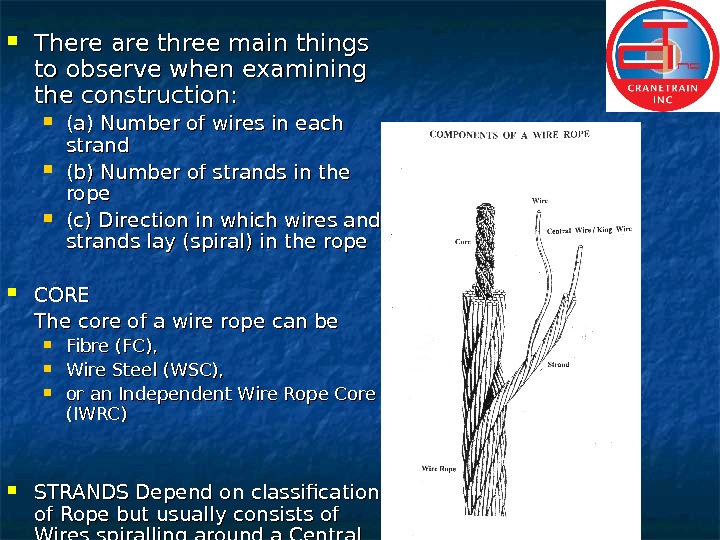
There are three main things to observe when examining the construction: (a) Number of wires in each strand (b) Number of strands in the rope (c) Direction in which wires and strands lay (spiral) in the rope CORE The core of a wire rope can be Fibre (FC), Wire Steel (WSC), or an Independent Wire Rope Core (IWRC) STRANDS Depend on classification of Rope but usually consists of Wires spiralling around a Central Core Wire
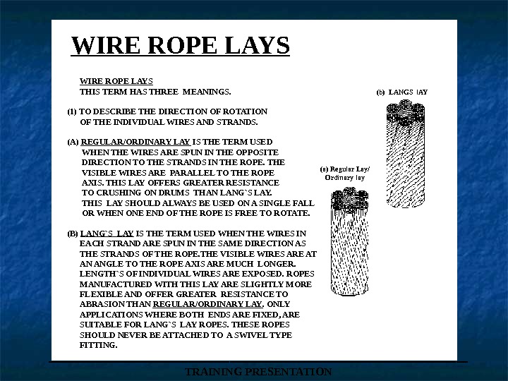
WIRE ROPE LAYS (b) LANGS l. AY (a) Regular Lay/ Ordinary lay WIRE ROPE LAYS THIS TERM HAS THREE MEANINGS. (1) TO DESCRIBE THE DIRECTION OF ROTATION OF THE INDIVIDUAL WIRES AND STRANDS. (A) REGULAR/ORDINARY LAY IS THE TERM USED WHEN THE WIRES ARE SPUN IN THE OPPOSITE DIRECTION TO THE STRANDS IN THE ROPE. THE VISIBLE WIRES ARE PARALLEL TO THE ROPE AXIS. THIS LAY OFFERS GREATER RESISTANCE TO CRUSHING ON DRUMS THAN LANG`S LAY. THIS LAY SHOULD ALWAYS BE USED ON A SINGLE FALL OR WHEN ONE END OF THE ROPE IS FREE TO ROTATE. (B) LANG`S LAY IS THE TERM USED WHEN THE WIRES IN EACH STRAND ARE SPUN IN THE SAME DIRECTION AS THE STRANDS OF THE ROPE. THE VISIBLE WIRES ARE AT AN ANGLE TO THE ROPE AXIS ARE MUCH LONGER. LENGTH`S OF INDIVIDUAL WIRES ARE EXPOSED. ROPES MANUFACTURED WITH THIS LAY ARE SLIGHTLY MORE FLEXIBLE AND OFFER GREATER RESISTANCE TO ABRASION THAN REGULAR/ORDINARY LAY. ONLY APPLICATIONS WHERE BOTH ENDS ARE FIXED, ARE SUITABLE FOR LANG`S LAY ROPES. THESE ROPES SHOULD NEVER BE ATTACHED TO A SWIVEL TYPE FITTING. ___________________ TRAINING PRESENTATION
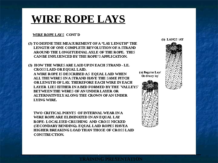
WIRE ROPE LAYS (b) LANGS l. AY (a) Regular Lay/ Ordinary lay WIRE ROPE LAYS CONT`D (2) TO DEFINE THE MEASUREMENT OF A “LAY LENGTH” THE LENGTH OF ONE COMPLETE REVOLUTION OF A STRAND AROUND THE LONGITUDINAL AXLE OF THE ROPE. THIS CAN BE INFLUENCED BY THE ROPE’S APPLICATION. (3) HOW THE WIRES ARE LAID UP IN EACH STRAND — I. E. CROSS LAID OR EQUAL LAID. A WIRE ROPE IS DESCRIBED AS EQUAL LAID WHEN ALL THE WIRES IN A STRAND HAVE THE SAME PITCH OR LENGTH OF LAY. THEREFORE EACH WIRE IN EACH LAYER LIES EITHER IN A BED FORMED BY THE `VALLEYS` BETWEEN THE WIRES OF AN UNDER LAYER OR ALTERNATIVELY ALONG THE CROWN OF AN UNDER LYING WIRE. TWO CRITICAL POINTS OF INTERNAL WEAR IN A WIRE ROPE ARE ELIMINATED IN AN EQUAL LAY ROPE- LOCALISED CRUSHING AND CROSS NICKED (SECONDARY BENDING). EQUAL LAID ROPES HAVEA HIGHER BREAKING LOAD THAN THOSE OF CROSS LAID CONSTRUCTION. ___________________ TRAINING PRESENTATION
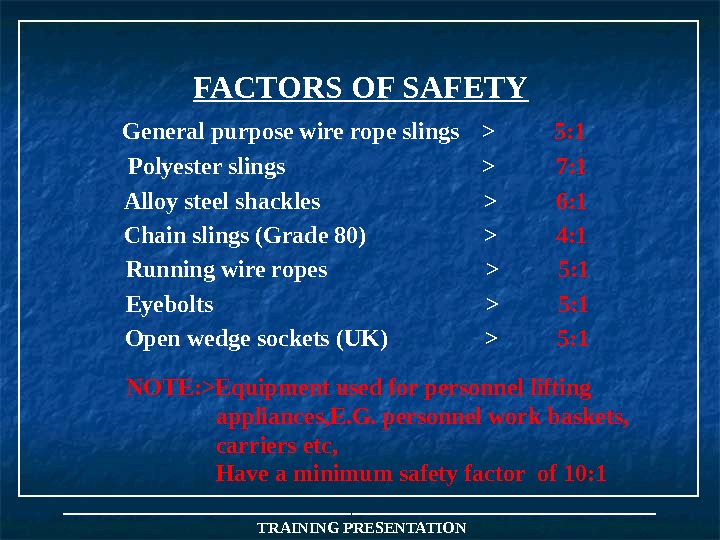
FACTORS OF SAFETY NOTE: >Equipment used for personnel lifting appliances, E. G. personnel work baskets, carriers etc, Have a minimum safety factor of 10: 1 ___________________ TRAINING PRESENTATIONGeneral purpose wire rope slings > 5: 1 Polyester slings > 7: 1 Alloy steel shackles > 6: 1 Chain slings (Grade 80) > 4: 1 Running wire ropes > 5: 1 Eyebolts > 5: 1 Open wedge sockets (UK) > 5:
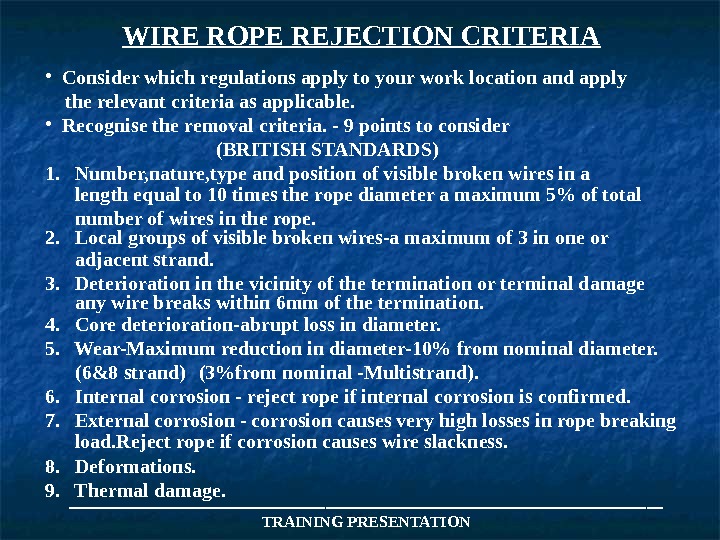
WIRE ROPE REJECTION CRITERIA • Consider which regulations apply to your work location and apply the relevant criteria as applicable. • Recognise the removal criteria. — 9 points to consider (BRITISH STANDARDS) 1. Number, nature, type and position of visible broken wires in a length equal to 10 times the rope diameter a maximum 5% of total number of wires in the rope. 2. Local groups of visible broken wires-a maximum of 3 in one or adjacent strand. 3. Deterioration in the vicinity of the termination or terminal damage any wire breaks within 6 mm of the termination. 4. Core deterioration-abrupt loss in diameter. 5. Wear-Maximum reduction in diameter-10% from nominal diameter. (6&8 strand) (3%from nominal -Multistrand). 6. Internal corrosion — reject rope if internal corrosion is confirmed. 7. External corrosion — corrosion causes very high losses in rope breaking load. Reject rope if corrosion causes wire slackness. 8. Deformations. 9. Thermal damage. ___________________ TRAINING PRESENTATION
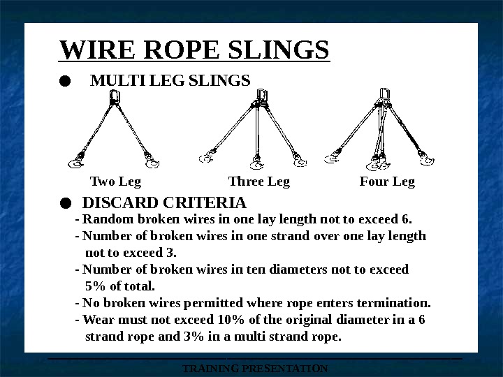
___________________ TRAINING PRESENTATIONWIRE ROPE SLINGS. MULTI LEG SLINGS Two Leg Three Leg Four Leg. DISCARD CRITERIA — Random broken wires in one lay length not to exceed 6. — Number of broken wires in one strand over one lay length not to exceed 3. — Number of broken wires in ten diameters not to exceed 5% of total. — No broken wires permitted where rope enters termination. — Wear must not exceed 10% of the original diameter in a 6 strand rope and 3% in a multi strand rope.
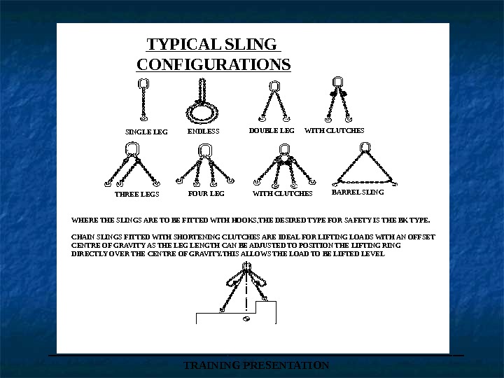
___________________ TRAINING PRESENTATIONTYPICAL SLING CONFIGURATIONS SINGLE LEG ENDLESS DOUBLE LEG WITH CLUTCHES THREE LEGS FOUR LEG BARREL SLING WITH CLUTCHES WHERE THE SLINGS ARE TO BE FITTED WITH HOOKS, THE DESIRED TYPE FOR SAFETY IS THE BK TYPE. CHAIN SLINGS FITTED WITH SHORTENING CLUTCHES ARE IDEAL FOR LIFTING LOADS WITH AN OFFSET CENTRE OF GRAVITY AS THE LEG LENGTH CAN BE ADJUSTED TO POSITION THE LIFTING RING DIRECTLY OVER THE CENTRE OF GRAVITY. THIS ALLOWS THE LOAD TO BE LIFTED LEVEL
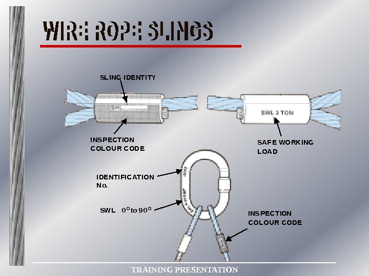
SW L 0 O to 9 0 O SL I NG I DE NT I TY I NS PEC T ION COL OU R C OD E SAF E WO RKI NG L OA D I DE NT I FI C AT ION N o. I NS PEC T ION C OL OU R C ODE___________________ TRAINING PRESENTATION
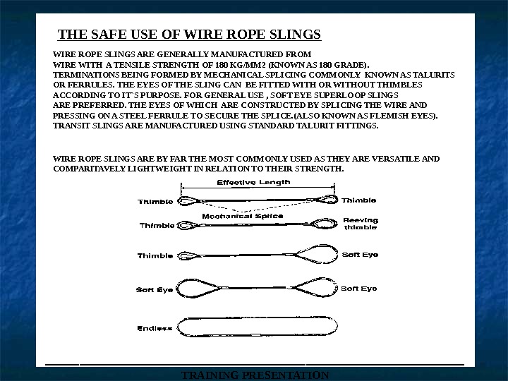
___________________ TRAINING PRESENTATIONTHE SAFE USE OF WIRE ROPE SLINGS ARE GENERALLY MANUFACTURED FROM WIRE WITH A TENSILE STRENGTH OF 180 KG/MM 2 (KNOWN AS 180 GRADE). TERMINATIONS BEING FORMED BY MECHANICAL SPLICING COMMONLY KNOWN AS TALURITS OR FERRULES. THE EYES OF THE SLING CAN BE FITTED WITH OR WITHOUT THIMBLES ACCORDING TO IT`S PURPOSE. FOR GENERAL USE , SOFT EYE SUPERLOOP SLINGS ARE PREFERRED. THE EYES OF WHICH ARE CONSTRUCTED BY SPLICING THE WIRE AND PRESSING ON A STEEL FERRULE TO SECURE THE SPLICE. (ALSO KNOWN AS FLEMISH EYES). TRANSIT SLINGS ARE MANUFACTURED USING STANDARD TALURIT FITTINGS. WIRE ROPE SLINGS ARE BY FAR THE MOST COMMONLY USED AS THEY ARE VERSATILE AND COMPARITAVELY LIGHTWEIGHT IN RELATION TO THEIR STRENGTH.
___________________ TRAINING PRESENTATION
___________________ TRAINING PRESENTATIONSLING ANGLES 0° 30° 60° 90° 120° 0. 5 te each sling 0. 53 te each sling 0. 58 te each sling 0. 7 te each sling 1. 0 Tonne The SWL of a pair of single slings decreases as the angle between them increases. 0°-SWL=SWL of one sling x 2 30°-SWL=SWL of one sling x 2 x 0. 966 60°-SWL=SWL of one sling x 2 x 0. 866 90°-SWL=SWL of one sling x 2 x 0. 707 120°-SWL=SWL of one sling x 2 x 0. 5 0°-SWL=SWL of one sling x 2 30°-SWL=SWL of one sling x 1. 93 60°-SWL=SWL of one sling x 1. 73 90°-SWL=SWL of one sling x 1. 414 120°-SWL=SWL of one sling only.
___________________ TRAINING PRESENTATIONW X L No X H
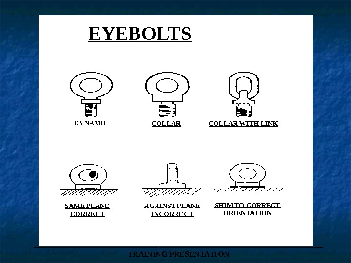
___________________ TRAINING PRESENTATIONEYEBOLTS-(BS 4278) COLLAR EYEBOLT DYNAMO EYEBOLT WITH LINK SHOULD BE USED FOR VERTICAL LIFTS OR O º ONLY INTENDED FOR GENERAL LIFTING ARE INTENDED FOR PERMANENT ATTACHMENT TO HEAVY PIECES OF EQUIPMENT AND ARE USUALLY FITTED IN PAIRS
___________________ TRAINING PRESENTATIONEYEBOLTS DYNAMO COLLAR WITH LINK. SAME PLANE CORRECT AGAINST PLANE INCORRECT SHIM TO CORRECT ORIENTATION
___________________ TRAINING PRESENTATION
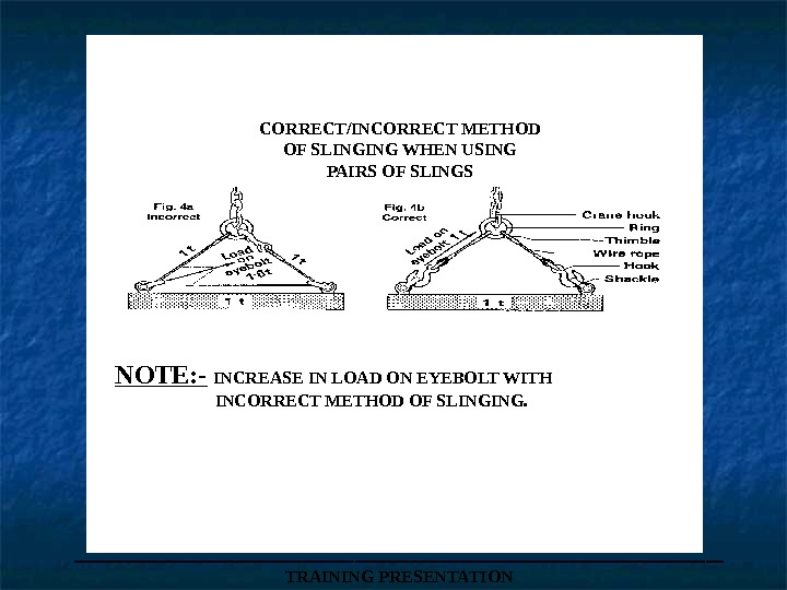
___________________ TRAINING PRESENTATIONCORRECT/INCORRECT METHOD OF SLINGING WHEN USING PAIRS OF SLINGS NOTE: — INCREASE IN LOAD ON EYEBOLT WITH INCORRECT METHOD OF SLINGING.
SINGLE VERTICAL LIFT 0 º ONLY ___________________ TRAINING PRESENTATIONDYNAMO EYEBOLT
___________________ TRAINING PRESENTATIONEYEBOLT CHART RECOMMENDED S. W. L. LOADS
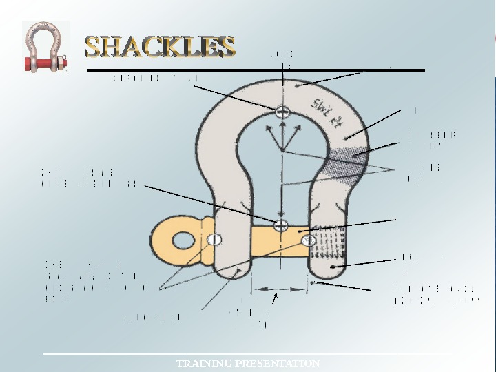
DEE TYPE SHACKLE (With screw pin) BOW TYPE SAFETY SHACKLE (With round bolt & safety pin)___________________ TRAINING PRESENTATION
___________________ TRAINING PRESENTATION
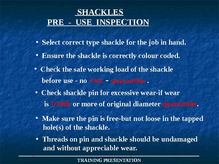
___________________ TRAINING PRESENTATION SHACKLES PRE — USE INSPECTION • Select correct type shackle for the job in hand. • Check the safe working load of the shackle before use — no SWL — quarantine . • Check shackle pin for excessive wear-if wear is 1/10 th or more of original diameter quarantine. • Make sure the pin is free-but not loose in the tapped hole(s) of the shackle. • Threads on pin and shackle should be undamaged and without appreciable wear. • Ensure the shackle is correctly colour coded.
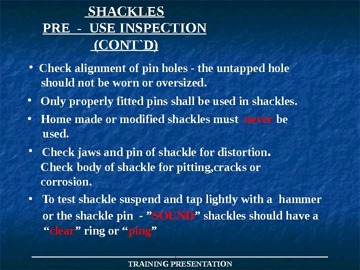
___________________ TRAINING PRESENTATION SHACKLES PRE — USE INSPECTION (CONT`D) • Check alignment of pin holes — the untapped hole should not be worn or oversized. • Only properly fitted pins shall be used in shackles. • Home made or modified shackles must never be used. • Check jaws and pin of shackle for distortion. Check body of shackle for pitting, cracks or corrosion. • To test shackle suspend and tap lightly with a hammer or the shackle pin — ” SOUND ” shackles should have a “ clear ” ring or “ ping ”
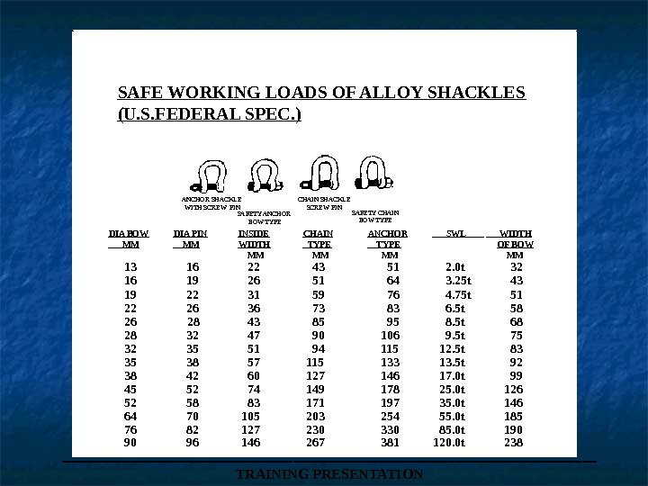
___________________ TRAINING PRESENTATIONSAFE WORKING LOADS OF ALLOY SHACKLES (U. S. FEDERAL SPEC. ) ANCHOR SHACKLE WITH SCREW PIN SAFETY ANCHOR BOW TYPE CHAIN SHACKLE SCREW PIN SAFETY CHAIN BOW TYPE DIA BOW DIA PIN INSIDE CHAIN ANCHOR SWL WIDTH MM MM WIDTH TYPE OF BOW MM MM 13 16 22 43 51 2. 0 t 32 16 19 26 51 64 3. 25 t 43 19 22 31 59 76 4. 75 t 51 22 26 36 73 83 6. 5 t 58 26 28 43 85 95 8. 5 t 68 28 32 47 90 106 9. 5 t 75 32 35 51 94 115 12. 5 t 83 35 38 57 115 133 13. 5 t 92 38 42 60 127 146 17. 0 t 99 45 52 74 149 178 25. 0 t 126 52 58 83 171 197 35. 0 t 146 64 70 105 203 254 55. 0 t 185 76 82 127 230 330 85. 0 t 190 90 96 146 267 381 120. 0 t
END OF DAY TWO
___________________ TRAINING PRESENTATION
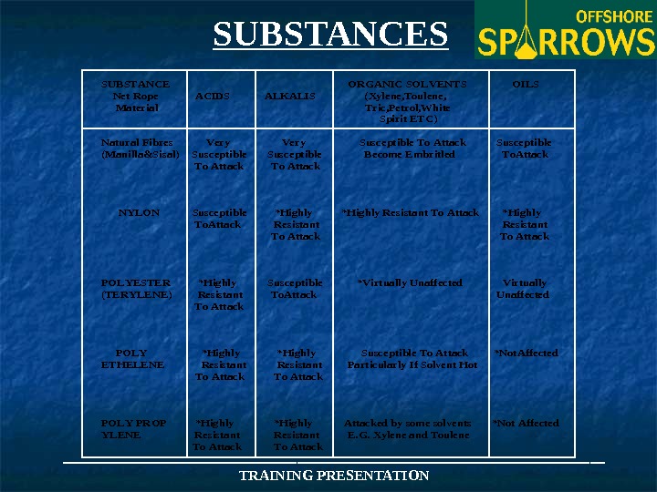
___________________ TRAINING PRESENTATIONSUBSTANCEORGANIC SOLVENTSOILS Net Rope ACIDS ALKALIS (Xylene, Toulene, Material Tric, Petrol, White Spirit ETC) Natural Fibres Very Susceptible To Attack Susceptible (Manilla&Sisal) Susceptible Become Embritled To. Attack To Attack NYLON Susceptible *Highly Resistant To Attack *Highly To. Attack Resistant To Attack To Attack POLYESTER *Highly Susceptible *Virtually Unaffected Virtually (TERYLENE) Resistant To. Attack Unaffected To Attack POLY *Highly Susceptible To Attack *Not. Affected ETHELENE Resistant. Particularly If Solvent Hot To Attack POLY PROP *Highly Attacked by some solvents *Not Affected YLENE Resistant. E. G. Xylene and Toulene To Attack. SUBSTANCES
___________________ TRAINING PRESENTATION
PLATE CLAMPS • TWO BASIC TYPES AVAILABLE • Horizontal clamps can only be used in pairs. • Universal clamps can be used individually. • When using Universal clamps in pairs you must use a spreader beam. Locking mechanism Plate Horizontal clamps Universal clamps (vertical) ___________________ TRAINING PRESENTATION
___________________ TRAINING PRESENTATIONWIRE ROPE CLIPS ( BULLDOGS)
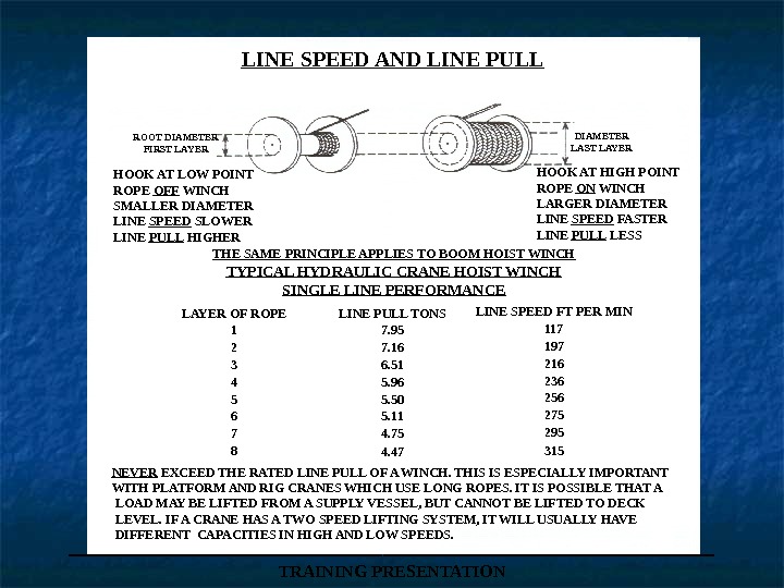
___________________ TRAINING PRESENTATIONLINE SPEED AND LINE PULL ROOT DIAMETER FIRST LAYER DIAMETER LAST LAYER NEVER EXCEED THE RATED LINE PULL OF A WINCH. THIS IS ESPECIALLY IMPORTANT WITH PLATFORM AND RIG CRANES WHICH USE LONG ROPES. IT IS POSSIBLE THAT A LOAD MAY BE LIFTED FROM A SUPPLY VESSEL, BUT CANNOT BE LIFTED TO DECK LEVEL. IF A CRANE HAS A TWO SPEED LIFTING SYSTEM, IT WILL USUALLY HAVE DIFFERENT CAPACITIES IN HIGH AND LOW SPEEDS. HOOK AT LOW POINT ROPE OFF WINCH SMALLER DIAMETER LINE SPEED SLOWER LINE PULL HIGHER HOOK AT HIGH POINT ROPE ON WINCH LARGER DIAMETER LINE SPEED FASTER LINE PULL LESS THE SAME PRINCIPLE APPLIES TO BOOM HOIST WINCH TYPICAL HYDRAULIC CRANE HOIST WINCH SINGLE LINE PERFORMANCE LAYER OF ROPE 1 2 3 4 5 6 7 8 LINE PULL TONS 7. 95 7. 16 6. 51 5. 96 5. 50 5. 11 4. 75 4. 47 LINE SPEED FT PER MIN
___________________ TRAINING PRESENTATIONREEVING WINCH WITH SINGLE LINE PULL OF 4 TONS ONE SHEAVE SINGLE PART LINE TWO SHEAVES 2 PART LINE LOAD= LINE PULL + THE NUMBER OF PARTS OF LINE THREE SHEAVES 3 PART LINE SIX SHEAVES 6 PART LINE HOOK SPEED= LINE SPEED DIVIDED BY PARTS OF LIN
___________________ TRAINING PRESENTATIONAngle of fleet The fleet angle is the angle formed between a line drawn from the centre of the pulley to the centre of the drum, and a line from the centre of the pulley to the inside edge of the drum flange. This angle should not exceed 1. 5°in the case of smooth drums, and 2°for grooved drums to ensure the minimum amount of side wear of rope against the adjacent warp in the case of smooth faced drums, and against the side of the grooves on grooved drums. A safe angle can be obtained by allowing at least 24 ft(7. 3 m) of lead for each 2 ft (0. 7 m)of drum width when the lead pulley is mounted on the centre line of the drum. FLEET ANGLES
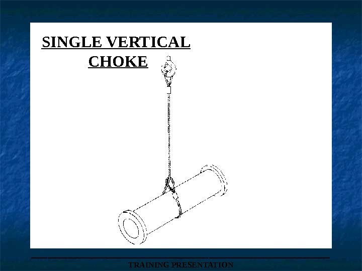
SINGLE VERTICAL CHOKE ___________________ TRAINING PRESENTATION
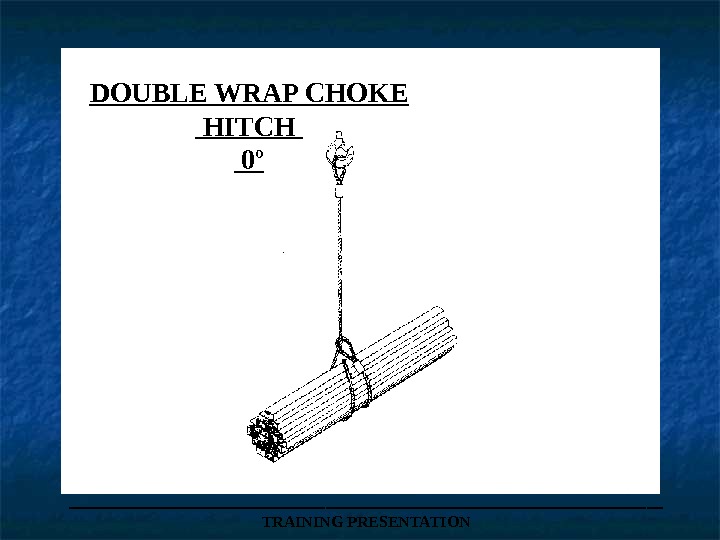
DOUBLE WRAP CHOKE HITCH 0º ___________________ TRAINING PRESENTATION
___________________ TRAINING PRESENTATIONDOUBLE WRAP CHOKE HITCH AT 90º THIS HITCH COMPRESSES THE LOAD AND PREVENTS IT FROM SLIPPING OUT. NOTE: THE TOTAL LOAD THAT MAY BE LIFTED WHEN THE INCLUDED ANGLE DOES NOT EXCEED 90°IS 1. 4 X THAT MARKED ON THE SINGLE SLING.
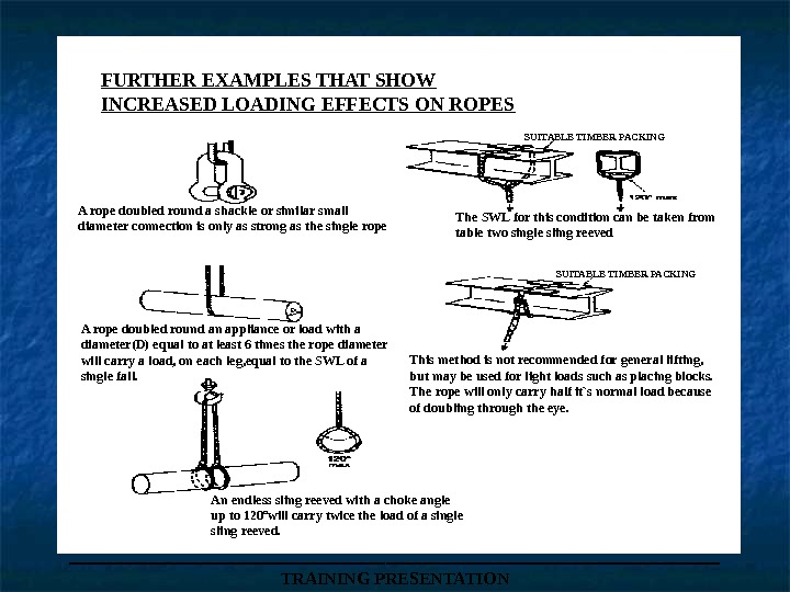
___________________ TRAINING PRESENTATIONFURTHER EXAMPLES THAT SHOW INCREASED LOADING EFFECTS ON ROPES SUITABLE TIMBER PACKINGA rope doubled round a shackle or similar small diameter connection is only as strong as the single rope The SWL for this condition can be taken from table two single sling reeved A rope doubled round an appliance or load with a diameter(D) equal to at least 6 times the rope diameter will carry a load, on each leg, equal to the SWL of a single fall. This method is not recommended for general lifting, but may be used for light loads such as placing blocks. The rope will only carry half it`s normal load because of doubling through the eye. An endless sling reeved with a choke angle up to 120ºwill carry twice the load of a single sling reeved.
CHAIN BLOCKS DISTANCE SUSP ENSION LEVE L TO OPE RATING LEVE L LOAD CHAIN ANC HOR POINT LOAD CHAIN MAI N CHAIN OPE RATING LEVE L TOP HO OK LOAD HO OK DRAW N-UP DIM ENSION RANGE OF LIFT BOTTOM HOOK FULLY EX TE NDED DIM ENSION CHAIN BLO CK O PERATING HEIGHT DIMENSION & TERMINOLO GY
___________________ TRAINING PRESENTATION
C he ck swi vel fo r fr eed om o f mo vem en t an d wea r C he ck pi vo t fo r wea r C he ck that h oo k cl ose s co r rec tly (N o g ap s) H oo k R ele ase C am C he ck for wea r an d cr acks C he ck that R el ease La tch o pe rate s fr eely_______________________________ TRAINING PRESENTATIONGUNNEBO HOOKS
___________________ TRAINING PRESENTATIONRIGHT AND WRONG PULLEY GROOVES WRONG PULLEY GROOVE TOO NARROW WRONG PULLEY GROOVE TOO WIDE RIGHT PULLEY GROOVE CORRECT. 120º OR 1/3 rd OF ROPE IS SUPPORT
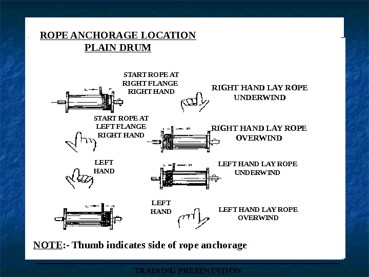
ROPE ANCHORAGE LOCATION PLAIN DRUM START ROPE AT RIGHT FLANGE RIGHT HAND LAY ROPE UNDERWIND START ROPE AT LEFT FLANGE RIGHT HAND LAY ROPE OVERWIND LEFT HAND LAY ROPE UNDERWIND LEFT HAND LAY ROPE OVERWIND NOTE : — Thumb indicates side of rope anchorage ___________________ TRAINING PRESENTATION
When spooling wire rope from a wooden drum onto the winch drum, avoid reverse bending which is detrimental to the lay of the rope. Always reel from top to top or bottom to bottom Never reel from top to bottom or bottom to top. ROPE CHANGEOUT Wrong Right ___________________ TRAINING PRESENTATION
___________________ TRAINING PRESENTATIONMEASUREMENT OF ROPE DIAMETERS CORRECT WAY THIS GIVES CORRECT DIAMETER INCORRECT WAY THIS DOES NOT GIVE THE CORRECT MEASUREMENT DIAMETER TOLERANCES Nominal rope Oversize Diameter (inches) 0 -3/4 +1/32 1 3/16 -1 1/8 +3/64 1 3/16 -1 1/2 +1/16 1 9/16 -2 1/4 +3/32 2 5/16 -UP +1/
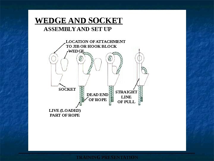
___________________ TRAINING PRESENTATIONLOCATION OF ATTACHMENT TO JIB OR HOOK BLOCK WEDGE SOCKET DEAD END OF ROPE STRAIGHT LINE OF PULL LIVE (LOADED) PART OF ROPEWEDGE AND SOCKET ASSEMBLY AND SET UP
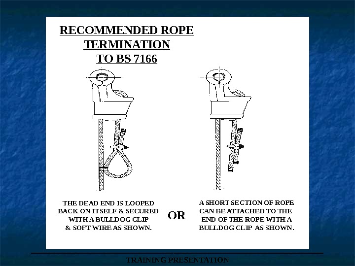
___________________ TRAINING PRESENTATIONRECOMMENDED ROPE TERMINATION TO BS 7166 THE DEAD END IS LOOPED BACK ON ITSELF & SECURED WITH A BULLDOG CLIP & SOFT WIRE AS SHOWN. A SHORT SECTION OF ROPE CAN BE ATTACHED TO THE END OF THE ROPE WITH A BULLDOG CLIP AS SHOWN. OR
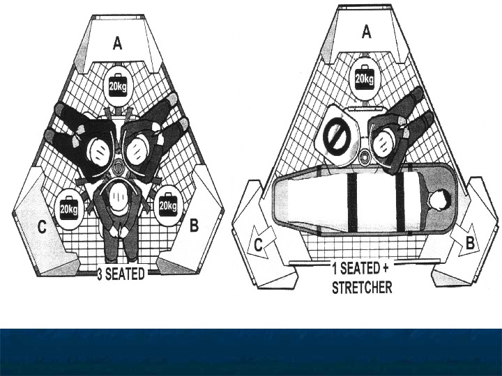
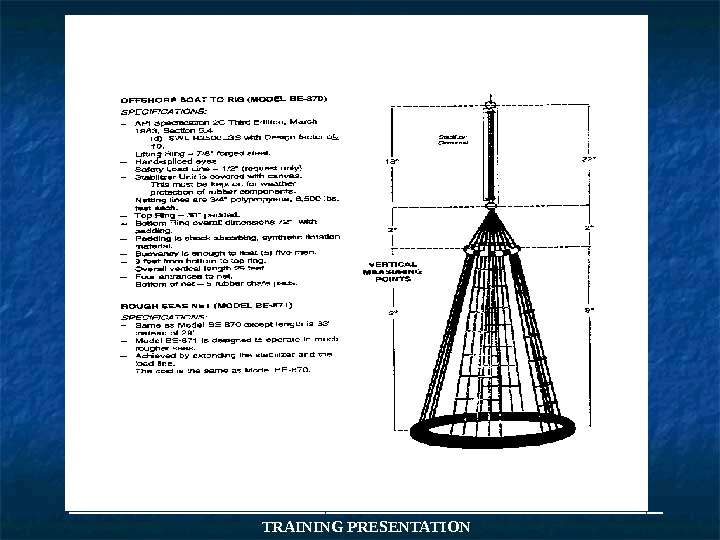
APPROVED PERSONNEL NETS ___________________ TRAINING PRESENTATION(Billy Pugh)
ARE THERE ANY QUESTIONS?
END OF PRESENTATION