
INTEL 8051 INSTRUCTION DEFINITIONS INSTRUCTION DEFINITIONS ACALL


ins_set_lec_9_11.ppt
- Размер: 462.5 Кб
- Количество слайдов: 77
Описание презентации INTEL 8051 INSTRUCTION DEFINITIONS INSTRUCTION DEFINITIONS ACALL по слайдам
INTEL 8051 INSTRUCTION DEFINITIONS
INSTRUCTION DEFINITIONS ACALL addr 11 Function: Absolute Call Description: ACALL unconditionally calls a subroutine located at the indicated address. The instruction increments the PC twice to obtain the address of the following instruction, then pushes the 16 -bit result onto the stack (low-order byte first) and increments the Stack Pointer twice. The destination address is obtained by successively concatenating the five high-order bits of the incremented PC, opcode bits 7 -5, and the second byte of the instruction. The subroutine called must therefore start within the same 2 K block of the program memory as the f. Irst byte of the instruction following ACALL. No flags are affected. Example: Initially SP equals 07 H. The label «SUBRTN» is at program memory location 0345 H. After executing the instruction,
INSTRUCTION DEFINITIONS ACALL SUBRTN at location 0123 H, SP will contain 09 H, internal RAM locations 08 H and 09 H will contain 25 H and 01 H, respectively, and the PC will contain 0345 H. Bytes: 2 Cycles: 2 Encoding: Operation: ACALL (PC) + 2 (SP) + 1 «SP» (PC 7 -0) (SP) + 1 «SP» (PC 15 -8) (PC 10 -0) page address
INSTRUCTION DEFINITIONS ADD A, Function : Add Description : ADD adds the byte variable indicated to the Accumulator, leaving the result in the Accumulator. The carry and auxiliary-carry flags are set, respectively, if there is a carry-out from bit 7 or bit 3, and cleared otherwise. When adding unsigned integers, the carry flag indicates an overflow occurred. OV is set if there is a carry-out of bit 6 but not out of bit 7, or a carry-out of bit 7 but not bit 6; otherwise OV is cleared. When adding signed integers, OV indicates a negative number produced as the sum of two positive operands, or a positive sum from two negative operands. Four source operand addressing modes are allowed: register, direct, register-indirect, or immediate. Example : The Accumulator holds OC 3 H (11000011 B) and register 0 holds OAAH (101010 l 0 B). The instruction, ADD A, R 0 will leave 6 DH (01101101 B) in the Accumulator with the AC flag cleared and both the carry flag and OV set to 1.
INSTRUCTION DEFINITIONS ADD A, Rn Bytes : 1 Cycles : 1 Encoding: Operation: ADD ( A ) (A) + (Rn) ADD A, direct Bytes: 2 Cycles: 1 Encoding: Operation: ADD (A) + (direct)
INSTRUCTION DEFINITIONS ADDC A, Function : Add with Carry Description : ADDC simultaneously adds the byte variable indicated, the carry flag and the Accumulator contents, leaving the result in the Accumulator. The carry and auxiliary-carry flags are set, respectively, if there is a carry-out from bit 7 or bit 3, and cleared otherwise. When adding unsigned integers, the carry flag indicates an overflow occurred. OV is set if there is a carry-out of bit 6 but not out of bit 7, or a carry-out of bit 7 but not out of bit 6; otherwise OV is cleared. When adding signed integers, OV indicates a negative number produced as the sum of two positive operands or a positive sum from two negative operands. Four source operand addressing modes are allowed: register, direct, register-indirect, or immediate. Example : The Accumulator holds OC 3 H (1 100001 1 B) and register 0 holds OAAH (1010 B) with the carry flag set. The instruction, ADDC A, R 0 wi 11 leave 6 EH (011011 l 0 B) in the Accumulator with AC cleared and both the Carry flag and OV set to 1.
INSTRUCTION DEFINITIONS ADDC A, Rn Bytes : 1 Cycles : 1 Encoding Operation: ADDC (A) + (C) + (Rn) ADDC A, direct Bytes: 2 Cycles: 1 Encoding: Operation: ADDC (A) + (C) + (direct)
INSTRUCTION DEFINITIONS ADDC A, @Ri Bytes : 1 Cycles : 1 Encoding : Operation: ADDC ( A ) (A) + (C) +(RJ) ADDC A, # data Bytes: 2 Cycles: 1 Encoding: Operation: ADDC (A) + (C) + #data
INSTRUCTION DEFINITIONS AJMP addr 11 Function: Absolute Jump Description: AJMP transfers program execution to the indicated address, which is formed at run-time by concatenating the high-order five bits of the PC (after incrementing the PC twice), opcode bits 7 -5, and the second byte of the instruction. The destination must therefore be within the same 2 K block of program memory as the first byte of the instruction following AJMP. Example: The label «JMPADR» is at program memory location 0123 H. The instruction, AJMP JMPADR is at location 0345 H and will load the PC with 0123 H. Bytes: 2 Cycles: 2 Encoding: Operation: AJMP (PC) + 2 (PC 10 -0) page address
INSTRUCTION DEFINITIONS ANL , Function: Logical-AND for byte variables Description: ANL performs the bitwise logical-AND operation between the variables indicated and stores the results in the destination variable. No flags are affected. The two operands allow six addressing mode combinations. When the destination is the Accumulator, the source can use register, direct, register-indirect, or immediate addressing; when the destination is a direct address, the source can be the Accumulator or immediate data. Note: When this instruction is used to modify an output port, the value used as the original port data will be read from the output data latch, not the input pins. Example: If the Accumulator holds OC 3 H (ll 0000 ll. B) and register 0 holds 55 H (0101 B) then the instruction, ANL A, R 0 will leave 4 l. H (01000001 B) in the Accumulator. When the destination is a directly addressed byte, this instruction will clear combinations of bits in any RAM location or hardware register. The mask byte detonating the pattern of bits to be cleared would either be a constant contained in the instruction or a value computed in the Accumulator at run-time. The instruction,
INSTRUCTION DEFINITIONS ANL P 1, #01110011 B will clear bits 7, 3, and 2 of output port 1. ANL A, Rn Bytes: 1 Cycles: 1 Encoding: Operation: ANL (A) 1 (Rn) ANL A, direct Bytes: 2 Cycles: 1 Encoding: Operation: ANL (A) (direct)
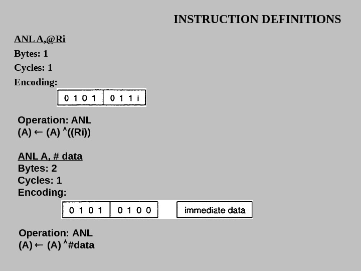
INSTRUCTION DEFINITIONS ANL A, @Ri Bytes: 1 Cycles: 1 Encoding: Operation: ANL (A) ((Ri)) ANL A, # data Bytes: 2 Cycles: 1 Encoding: Operation: ANL (A) #data
INSTRUCTION DEFINITIONS ANL direct, A Bytes: 2 Cycles: 1 Encoding: Operation: ANL (direct) (A) ANL direct, # data Bytes : 3 Cycles: 2 Encoding: Operation: ANL (direct) #data
INSTRUCTION DEFINITIONS ANL C, Function : Logical-AND for bit variables Description : If the Boolean value of the source bit is a logical 0 then clear the carry flag; otherwise leave the carry flag in its current state. A slash («I») preceding the operand in the assembly language indicates that the logical complement of the addressed bit is used as the source value, but the source bit itself is not affected. No other flags are affected. Only direct addressing is allowed for the source operand. Example : Set the carry flag if, and only if, P 1. 0 = 1, ACe. 7 = 1, and OV = 0: MOV C, P 1. 0 ; LOAD CARRY WITH INPUT PIN STATE ANL C, ACC. 7 ; AND CARRY WITH ACCUM. BIT 7 ANL C, /OV ; AND WITH INVERSE OF OVERFLOW FLAG ANL C, bit Bytes : 2 Cycles : 2 Encoding: Operation: ANL (C) 1 (bit)
INSTRUCTION DEFINITIONS CJNE , , rei Function : Compare and Jump if Not Equal. Description : CJNE compares the magnitudes of the first two operands, and branches if their values are not equal. The branch destination is computed by adding the signed relative-displacement in the last instruction byte to the PC, after incrementing the PC to the start of the next instruction. The carry flag is set if the unsigned integer value of is less than the unsigned integer value of ; otherwise, the carry is cleared. Neither operand is affected. The first two operands allow four addressing mode combinations: the Accumulator may be compared with any directly addressed byte or immediate data, and any indirect RAM location or working register can be compared with an immediate constant. Example : The Accumulator contains 34 H. Register 7 contains 56 H. The first instruction in the sequence, CJNE R 7, #60 H, NOT_EQ ; … …. . ; R 7 = 60 H. NOT_EQ: JC REQ_LOW ; IFR 7 6 OH.
INSTRUCTION DEFINITIONS sets the carry flag and branches to the instruction at label NOTJQ. By testing the carry flag, this instruction determines whether R 7 is greater or less than 60 H. If the data being presented to Port I is also 34 H, then the instruction, WAIT: CJNE A, PI, WAIT clears the carry flag and continues with the next instruction in sequence, since the Accumulator does equal the data read from PI. (If some other value was being input on PI, the program will loop at this point until the PI data changes to 34 H. ) CJNE A, direct, rel Bytes : 3 Cycles : Encoding :
INSTRUCTION DEFINITIONS Operation: (PC) + 3 IF (A) (direct) THEN (PC) +- (PC) + relative offtet IF (A) < (direct) THEN (C) 1 ELSE (C) 0 CLR bit Function : Clear bit Description : The indicated bit is cleared (reset to zero). No other flags are affected. CLR can operate on the carry flag or any directly addressable bit. Example : Port 1 has previously been written with 5 DH (01011101 B). The instruction, CLR P 1. 2 will leave the port set to 59 H (01011001 B).
INSTRUCTION DEFINITIONS CPL bit Function: Complement bit Description: The bit variable specified is complemented. A bit which had been a one is changed to zero and vice-versa. No other flags are affected. CLR can operate on the carry or any directly addressable bit. Note: When this instruction is used to modify an output pin, the value used as the original data will be read from the output data latch, not the input pin. Example: Port 1 has previously been written with SBH (01011101 B). The instruction sequence, CPL Pl. l CPL Pl. 2 wi 11 leave the port set to SBH (01011011 B). DA A Function: Decimal-adjust Accumulator for Addition Description: DA A adjusts the eight-bit value in the Accumulator resulting from the earlier addition of two variables (each in packed-BCD format), producing two four-bit digits. Any ADD or ADDC instruction may have been used to perform the addition. If Accumulator bits 3 -0 are greater than nine (xxxx 1010 -xxxx 1111), or if the AC flag is one, six is added to the Accumulator producing the proper BCD digit in the low-order nibble. This internal addition would set the carry flag if a carry-out of the low-order four-bit field propagated through all high-order bits, but it would not clear the carry flag otherwise
INSTRUCTION DEFINITIONS If the carry flag is now set, or if the four high-order bits now exceed nine (1010 xxxx-111 xxxx), these high-order bits are incremented by six, producing the proper BCD digit in the high-order nibble. Again, this would set the carry flag if there was a carry-out of the high-order bits, but wouldn’t clear the carry. The carry flag thus indicates if the sum of the original two BCD variables is greater than 100, allowing multiple precision decimal additions. OV is not affected. All of this occurs during the one instruction cycle. Essentially, this instruction performs the decimal conversion by adding OOH, 06 H, 6 OH, or 66 H to the Accumulator, depending on initial Accumulator and PSW conditions. Note: DA A cannot simply convert a hexadecimal number in the Accumulator to BCD notation, nor does DA A apply to decimal subtraction. Example : The Accumulator holds the value 56 H (01010110 B) representing the packed BCD digits of the decimal number 56. Register 3 contains the value 67 H (01100111 B) representing the packed BCD digits of the decimal number 67. The carry flag is set. The instruction sequence: ADDC A, R
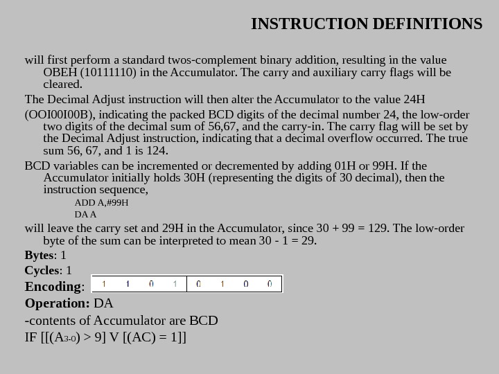
INSTRUCTION DEFINITIONS will first perform a standard twos-complement binary addition, resulting in the value OBEH (10111110) in the Accumulator. The carry and auxiliary carry flags will be cleared. The Decimal Adjust instruction will then alter the Accumulator to the value 24 H (OOI 00 B), indicating the packed BCD digits of the decimal number 24, the low-order two digits of the decimal sum of 56, 67, and the carry-in. The carry flag will be set by the Decimal Adjust instruction, indicating that a decimal overflow occurred. The true sum 56, 67, and 1 is 124. BCD variables can be incremented or decremented by adding 01 H or 99 H. If the Accumulator initially holds 30 H (representing the digits of 30 decimal), then the instruction sequence, ADD A, #99 H DA A will leave the carry set and 29 H in the Accumulator, since 30 + 99 = 129. The low-order byte of the sum can be interpreted to mean 30 — 1 = 29. Bytes : 1 Cycles : 1 Encoding : Operation: DA -contents of Accumulator are BCD IF [[(A 3 -0 ) > 9] V [(AC) = 1]]
INSTRUCTION DEFINITIONS THEN(A 3 -0) + 6 AND IF [[(A 7 -4) > 9] V [(C) = 1]] THEN (A 7 -4) + 6 DEC byte Function: Decrement Description: DEC byte decrements the variable indicated by 1. An original value of 00 H underflows to 0 FFH. No flags are affected. Four operand addressing modes are allowed: accumulator, register, direct, or register-indirect. Note : When this instruction is used to modify an output port, the value used as the original port data will be read from the output data latch, not the input pins. Example: Register 0 contains 7 FH (01111111 B). Internal RAM locations 7 EH and 7 FH contain 00 H and 40 H, respectively. The following instruction sequence, DEC @R 0 leaves register 0 set to 7 EH and internal RAM locations 7 EH and 7 FH set to 0 FFH and 3 FH.
INSTRUCTION DEFINITIONS DEC A Bytes: 1 Cycles: 1 Encoding: Operation: DEC (A) ← (A) — 1 DEC Rn Bytes: 1 Cycles: 1 Encoding: Operation: DEC (Rn) ← (Rn) — 1 DEC direct Bytes: 2 Cycles: 1 Encoding: Operation: DEC (direct) ← (direct) –
INSTRUCTION DEFINITIONS DIV AB Function: Divide Description: DIV AB divides the unsigned eight-bit integer in the Accumulator by the unsigned eight-bit integer in register B. The Accumulator receives the integer part of the quotient; register B receives the integer remainder. The carry and OV flags are cleared. Exception : if B had originally contained 00 H, the values returned in the Accumulator and B-register are undefined and the overflow flag are set. The carry flag is cleared in any case. Example: The Accumulator contains 251 (0 FBH or 11111011 B) and B contains 18 (12 H or 00010010 B). The following instruction: DIV AB leaves 13 in the Accumulator (0 DH or 00001101 B) and the value 17 (11 H or 0001 B) in B, since 251 = (13 x 18) + 17. Carry and OV are both cleared. Bytes: 1 Cycles: 4 Encoding : Operation: DIV (A) 15 -8 ← (A)/(B) 7 —
INSTRUCTION DEFINITIONS DJNZ , Function: Decrement and Jump if Not Zero Description: DJNZ decrements the location indicated by 1, and branches to the address indicated by the second operand if the resulting value is not zero. An original value of 00 H underflows to 0 FFH. No flags are affected. The branch destination is computed by adding the signed relative-displacement value in the last instruction byte to the PC, after incrementing the PC to the first byte of the following instruction. The location decremented may be a register or directly addressed byte. Note : When this instruction is used to modify an output port, the value used as the original port data will be read from the output data latch, not the input pins. Example: Internal RAM locations 40 H, 50 H, and 60 H contain the values 01 H, 70 H, and 15 H, respectively. The following instruction sequence, DJNZ 40 H, LABEL_1 DJNZ 50 H, LABEL_2 DJNZ 60 H, LABEL_3 causes a jump to the instruction at label LABEL_2 with the values 00 H, 6 FH, and 15 H in the three RAM locations. The first jump was not taken because the result was zero. This instruction provides a simple way to execute a program loop a given number of times or for adding a moderate time delay (from 2 to 512 machine cycles) with a single instruction. The following instruction sequence: MOV R 2, # 8 TOGGLE: CPL P 1. 7 DJNZ R 2, TOGGL
INSTRUCTION DEFINITIONS toggles P 1. 7 eight times, causing four output pulses to appear at bit 7 of output Port 1. Each pulse lasts three machine cycles; two for DJNZ and one to alter the pin. DJNZ Rn, rel Bytes: 2 Cycles: 2 Encoding : Operation: DJNZ (PC) ← (PC) + 2 (Rn) ← (Rn) — 1 IF (Rn) > 0 or (Rn) 0 or (direct) < 0 THEN (PC) ← (PC) + rel
INSTRUCTION DEFINITIONS INC Function: Increment Description: INC increments the indicated variable by 1. An original value of 0 FFH overflows to 00 H. No flags are affected. Three addressing modes are allowed: register, direct, or register-indirect. Note: When this instruction is used to modify an output port, the value used as the original port data will be read from the output data latch, not the input pins. Example: Register 0 contains 7 EH (011111110 B). Internal RAM locations 7 EH and 7 FH contain 0 FFH and 40 H, respectively. The following instruction sequence: INC @R 0 leaves register 0 set to 7 FH and internal RAM locations 7 EH and 7 FH holding 00 H and 41 H, respectively. INC A Bytes: 1 Cycles: 1 Encoding: Operation: INC (A) ← (A) +
INSTRUCTION DEFINITIONS INC Rn Bytes: 1 Cycles: 1 Encoding: Operation: INC (Rn) ← (Rn) + 1 INC direct Bytes: 2 Cycles : 1 Encoding: Operation: INC (direct) ← direct) +
INSTRUCTION DEFINITIONS INC DPTR Function: Increment Data Pointer Description: INC DPTR increments the 16 -bit data pointer by 1. A 16 -bit increment (modulo 2 powered to 16) is performed, and an overflow of the low-order byte of the data pointer (DPL) from 0 FFH to 00 H increments the high-order byte (DPH). No flags are affected. This is the only 16 -bit register which can be incremented. Example: Registers DPH and DPL contain 12 H and 0 FEH, respectively. The following instruction sequence, INC DPTR changes DPH and DPL to 13 H and 01 H. Bytes: 1 Cycles: 2 Encoding: Operation: INC (DPTR) ← (DPTR) +
INSTRUCTION DEFINITIONS JB blt, rel Function: Jump if Bit set Description: If the indicated bit is a one, JB jump to the address indicated; otherwise, it proceeds with the next instruction. The branch destination is computed by adding the signed relative-displacement in the third instruction byte to the PC, after incrementing the PC to the first byte of the next instruction. The bit tested is not modified. No flags are affected. Example: The data present at input port 1 is 11001010 B. The Accumulator holds 56 (01010110 B). The following instruction sequence, JB P 1. 2, LABEL 1 JB ACC. 2, LABEL 2 causes program execution to branch to the instruction at label LABEL 2. Bytes: 3 Cycles: 2 Encoding: Operation: JB (PC) ← (PC) + 3 IF (bit) = 1 THEN (PC) ← (PC) + rel
INSTRUCTION DEFINITIONS JBC bit, rel Function: Jump if Bit is set and Clear bit Description: If the indicated bit is one, JBC branches to the address indicated; otherwise, it proceeds with the next instruction. The bit will not be cleared if it is already a zero. The branch destination is computed by adding the signed relative-displacement in the third instruction byte to the PC, after incrementing the PC to the first byte of the next instruction. No flags are affected. Note : When this instruction is used to test an output pin, the value used as the original data will be read from the output data latch, not the input pin. Example: The Accumulator holds 56 H (01010110 B). The following instruction sequence, JBC ACC. 3, LABEL 1 JBC ACC. 2, LABEL 2 causes program execution to continue at the instruction identified by the label LABEL 2, with the Accumulator modified to 52 H (01010010 B). Bytes: 3 Cycles: 2 Encoding: Operation: JBC (PC) ← (PC) + 3 IF (bit) = 1 THEN (bit) ← 0 (PC) ← (PC) +rel
INSTRUCTION DEFINITIONS JC rel Function: Jump if Carry is set Description: If the carry flag is set, JC branches to the address indicated; otherwise, it proceeds with the next instruction. The branch destination is computed by adding the signed relative-displacement in the second instruction byte to the PC, after incrementing the PC twice. No flags are affected. Example: The carry flag is cleared. The following instruction sequence, JC LABEL 1 CPL C JC LABEL 2 sets the carry and causes program execution to continue at the instruction identified by the label LABEL 2. Bytes: 2 Cycles: 2 Encoding: Operation: JC (PC) ← (PC) + 2 IF (C) = 1 THEN (PC) ← (PC) + rel
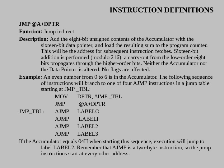
INSTRUCTION DEFINITIONS JMP @A+DPTR Function: Jump indirect Description: Add the eight-bit unsigned contents of the Accumulator with the sixteen-bit data pointer, and load the resulting sum to the program counter. This will be the address for subsequent instruction fetches. Sixteen-bit addition is performed (modulo 216): a carry-out from the low-order eight bits propagates through the higher-order bits. Neither the Accumulator nor the Data Pointer is altered. No flags are affected. Example: An even number from 0 to 6 is in the Accumulator. The following sequence of instructions will branch to one of four AJMP instructions in a jump table starting at JMP _TBL: MOV DPTR, #JMP _TBL JMP @A+DPTR JMP_TBL: AJMP LABELO AJMP LABELl AJMP LABEL 2 AJMP LABEL 3 If the Accumulator equals 04 H when starting this sequence, execution will jump to label LABEL 2. Remember that AJMP is a two-byte instruction, so the jump instructions start at every other address.
INSTRUCTION DEFINITIONS Bytes : 1 Cycles : 2 Encoding : Operation : JMP (PC) ~ (A) + (DPTR) JNB bit, rel Function : Jump if Bit Not set Description : If the indicated bit is a zero, branch to the indicated address; otherwise proceed with the next instruction. The branch destination is computed by adding the signed relative-displacement in the third instruction byte to the PC, after incrementing the PC to the first byte of the next instruction. The bit tested is not modified. No flags are affected. Example : The data present at input port 1 is 1 10010 l 0 B. The Accumulator holds 56 H (010101 l 0 B). The instruction sequence, JNB P 1. 3, LABELl JNB ACC. 3, LABEL 2 will cause program execution to continue at the instruction at label LABEL 2. Bytes : 1 Cycles : 2 Encoding :
INSTRUCTION DEFINITIONS Operation JNB (PC) ← (PC) + 3 IF (bit) = 0 THEN (PC) ← (PC) + re. I. JZ rei Function: Jump if Accumulator Zero Description: If all bits of the Accumulator are zero, branch to the address indicated; otherwise proceed with the next instruction. The branch destination is computed by adding the signed relative-displacement in the second instruction byte to the PC, after incrementing the PC twice. The Accumulator is not modified. No flags are affected. Example: The Accumulator originally contains OIH. The instruction sequence, JZ LABELl DEC A JZ LABEL 2 will change the Accumulator to OOH and cause program execution to continue at the instruction identified by the label LABEL 2.
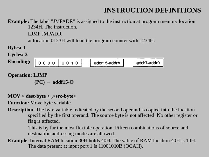
INSTRUCTION DEFINITIONS Bytes : 2 Cycles : 2 Encoding: Operation: LCALL (PC) ← (PC) + 3 (SP) ← (SP) + 1 «SP» ← (PC 7 -O) (SP) ← (SP) + 1 «SP» ← (PC 15 -S) (PC) ← addr 15 -O LJMP addr 16 Function: Long Jump Description: LJ MP causes an unconditional branch to the indicated address, by loading the high-order and low-order bytes of the PC (respectively) with the second and third instruction bytes. The destination may therefore be anywhere in the full 64 K program memory address space. No flags are affected.
INSTRUCTION DEFINITIONS Example: The label «JMPADR» is assigned to the instruction at program memory location 1234 H. The instruction, LJMP JMPADR at location 0123 H will load the program counter with 1234 H. Bytes: 3 Cycles: 2 Encoding: Operation: LJMP (PC) ← addf 15 -O MOV , Function : Move byte variable Description : The byte variable indicated by the second operand is copied into the location specified by the first operand. The source byte is not affected. No other register or flag is affected. This is by far the most flexible operation. Fifteen combinations of source and destination addressing modes are allowed. Example : Internal RAM location 30 H holds 40 H. The value of RAM location 40 H is 10 H. The data present at input port 1 is 11001010 B (OCAH).
INSTRUCTION DEFINITIONS MOV RO, #30 H ; RO <= 30 H MOV A, @RO ; A <= 40 H MOV Rl, A ; RI <= 40 H MOV B, @RI ; B <= l. OH MOV @RI, PI ; RAM (40 H) < = OCAH MOV P 2, PI ; P 2 #OCAH leaves the value 30 H in register 0, 40 H in both the Accumulator and register I, l 0 H in register B, and OCAH (1 100 10 l 0 B) both in RAM location 40 H and output on port 2 MOV A, Rn Bytes: 1 Cycles: 1 Encoding: Operation: MOV (A) ← (Rn)
INSTRUCTION DEFINITIONS MOV A, direct Bytes: 2 Cycles: Encoding: Operation: MOV (A) ←(direct) MOV A, ACC is not a valid instruction. MOV A, @Ri Bytes: 1 Cycles: 1 Encoding: Operation: MOV (A) ←(Ri)
INSTRUCTION DEFINITIONS MOV A, # data Bytes: 2 Cycles: 1 Encoding: Operation: MO V (A) ← #data MOV Rn, A Bytes: 1 Cycles: 1 Encoding: Operation : MO V (Rn) ← (A)
INSTRUCTION DEFINITIONS MOV Rn, direct Bytes : 2 Cycles : 2 Encoding: Operation: MOV (Rn) ← (direct) MOV Rn, # data Bytes : 2 Cycles : 2 Encoding: Operation: MOV (Rn) ← #data
INSTRUCTION DEFINITIONS MOV direct, A Bytes : 2 Cycles : 1 Encoding: Operation: MOV (direct) ← (A) MOV direct, Rn Bytes: 2 Cycles: 2 Encoding: Operation: MOV (direct) ← (Rn) MOV direct, direct Bytes: 3 Cycles: 2 Encoding:
INSTRUCTION DEFINITIONS Operation : MOV (direct) ← (direct) MOV direct, @Ri Bytes : 2 Cycles : 2 Encoding : Operation: MOV (direct) ← ((Ri)) MOV direct, # data Bytes: 3 Cycles: 2 Encoding : Operation: MOV (direct) ← #data
INSTRUCTION DEFINITIONS MOV @Ri, A Bytes: 1 Cycles: 1 Encoding: Operation: MOV (( Ri )) ← (A) MOV @Ri, direct Bytes: 2 Cycles: 2 Encoding: Operation : MOV ((Ri)) ← (direct)
INSTRUCTION DEFINITIONS MOV @Ri, # data Bytes: 2 Cycles: 1 Encoding: Operation: MOV (( RI )) ← #data MOV , Function: Move bit data Description: The Boolean variable indicated by the second operand is copied into the location specified by the first operand. One of the operands must be the carry flag; the other may be any directly addressable bit. No other register or flag is affected. Example: The carry flag is originally set. The data present at input Port 3 is 1 1 00010 1 B. The data previously written to output Port 1 is 35 H (00110101 B). MOV P 1. 3, C MOV C, P 3. 3 MOV P 1. 2, C will leave the carry cleared and change Port 1 to 39 H (0011100 l. B).
INSTRUCTION DEFINITIONS MOV C, bit Bytes : 2 Cycles: 1 Encoding: Operation: MOV (C) ← (bit) MOV bit, C Bytes : 2 Cycles : 2 Encoding: Operation: MOV (bit) ← (C)
INSTRUCTION DEFINITIONS MOV DPTR, #data 16 Function: Load Data Pointer with a 16 -bit constant Description: The Data Pointer is loaded with the 16 -bit constant indicated. The 16 -bit constant is loaded into the second and third bytes of the instruction. The second byte (DPH) is the high-order byte, while third byte (DPL) holds the low-order byte. No flags are affected. This is the only instruction which moves 16 bits of data at once. Example: The instruction, MOV DPTR, # 1234 H will load the value 1234 H into the Data Pointer: DPH will hold 12 H and DPL will hold 34 H. Bytes: 3 Cycles: 2 Encoding: Operation: MOV (DPTR) ← # data l 5 -0 DPH 0 DPL ← #datal 5 -8 0 #data 7 —
INSTRUCTION DEFINITIONS MOVC A, @A+ Function : Move Code byte Description : The MOVC instructions load the Accumulator with a code byte, or constant from program memory. The address of the byte fetched is the sum of the original unsigned eight-bit Accumulator contents and the contents of a sixteen-bit base register, which may be either the Data Pointer or the PC. In the latter case, the PC is incremented to the address of the following instruction before being added with the Accumulator; otherwise the base register is not altered. Sixteen-bit addition is performed so a carry-out from the low-order eight bits may propagate through higher-order bits. No flags are affected. Example : A value between 0 and 3 is in the Accumulator. The following instructions will translate the value in the Accumulator to one of four values defined by the DB (define byte) directive. REL_PC: INC A MOVC A, @A+PC RET DB 66 H DB 77 H DB 88 H DB 99 H If the subroutine is called with the Accumulator equal to Ol. H, it will return with 77 H in the Accumulator. The INC A before the MOVC instruction is needed to «get around» the RET instruction above the table. If several bytes of code separated the MOVC from the table, the corresponding number would be added to the Accumulator instead.
INSTRUCTION DEFINITIONS MOVC A, @A+DPTR Bytes : 1 Cycles : 2 Encoding: Operation : MOVC (A) ((A) + (DPT)) MOVC A, @A + PC Bytes : 1 Cycles: 2 Encoding: Operation : MOVC (PC) + 1 (A) ((A) + (PC))
INSTRUCTION DEFINITIONS MOVX , Function: Move External Description: The MOVX instructions transfer data between the Accumulator and a byte of external data memory, hence the «X» appended to MOV. There are two types of instructions, differing in whether they provide an eight-bit or sixteen-bit indirect address to the external data RAM. In the first type, the contents of RO or Rl in the current register bank provide an eight-bit address multiplexed with data on po. Eight bits are sufficient for external 1/0 expansion decoding or for a relatively small RAM array. For somewhat larger arrays, any output port pins can be used to output higher-order address bits. These pins would be controlled by an output instruction preceding the MOVX. In the second type of MOVX instruction, the Data Pointer generates a sixteen-bit address. P 2 outputs the high-order eight address bits (the contents of DPH) while po multiplexes the low order eight bits (DPL) with data. The P 2 Special Function Register retains its previous contents while the P 2 output buffers are emitting the contents of DPH. This form is faster and more efficient when accessing very large data arrays (up to 64 K bytes), since no additional instructions are needed to set up the output ports. It is possible in some situations to mix the two MOVX types. A large RAM array with its high-order address lines driven by P 2 can be addressed via the Data Pointer, or with code to output high-order address bits to P 2 followed by a MOVX instruction using RO or Rl.
INSTRUCTION DEFINITIONS Example: An external 256 byte RAM using multiplexed address data lines (e. g. , an Intel 8155 RAMI I/Ol. Timer) is connected to the 8051 Port O. Port 3 provides control lines for the external RAM. Ports 1 and 2 are used for nominal I/O. Registers 0 and 1 contain 12 H and 34 H. Location 34 H of the external RAM holds the value 56 H. The instruction sequence, MOVX A, @Rl MOVX @RO, A copies the value 56 H into both the Accumulator and external RAM location 12 H. MOVX A, @Ri Bytes: 1 Cycles: 2 Encoding: Operation: MOVX (A) ((Ri)) MOVX A, @DPTR Bytes: 1 Cycles: 2 Encoding: Operation MOVX (A) ((DPTR))
INSTRUCTION DEFINITIONS MOVX @Ri, A Bytes: 1 Cycles: 2 Encoding: Operation: MOVX ((Ri)) (A) MOVX @DPTR, A Bytes: 1 Cycles: 2 Encoding: Operation: MOVX (DPTR) (A)
INSTRUCTION DEFINITIONS MUL AB Function: Multiply Description: MUL AB multiplies the unsigned eight-bit integers in the Accumulator and register B. The low-order byte of the sixteen-bit product is left in the Accumulator, and the high-order byte in B. If the product is greater than 255 (OFFH) the overflow flag is set; otherwise it is cleared. The carry flag is always cleared. Example: Originally the Accumulator holds the value 80 (50 H). Register B holds the value 160 (OAOH). The instruction, MUL AB will give the product 12, 800 (3200 H), so B is changed to 32 H (OOII 00 l. OB) and the Accumulator is cleared. The overflow flag is set, carry is cleared. Bytes: 1 Cycles: 4 Encoding: Operation: MUL (A) 7 -O (A) X (B) B 15 —
INSTRUCTION DEFINITIONS NOP Function : No Operation Description : Execution continues at the following instruction. Other than the PC, no registers or flags are affected. Example : It is desired to produce a low-going output pulse on bit 7 of Port 2 lasting exactly 5 cycles. A simple SETB/CLR sequence would generate a one-cycle pulse, so four additional cycles must be inserted. This may be done (assuming no interrupts are enabled) with the instruction sequence, CLR P 2. 7 NOP NOP SETB P 2. 7 Bytes: 1 Cycles: 1 Encoding: Operation: NOP (PC) +
INSTRUCTION DEFINITIONS ORL Function: Logical-OR for byte variables Description: ORL performs the bitwise logical-OR operation between the indicated variables, storing the results in the destination byte. No flags are affected. The two operands allow six addressing mode combinations. When the destination is the Accumulator, the source can use register, direct, register- indirect, or immediate addressing; when the destination is a direct address, the source can be the Accumulator or immediate data. Note: When this instruction is used to modify an output port, the value used as the original port data will be read from the output data latch, not the input pins. Example: If the Accumulator holds 0 C 3 H (11000011 B) and R 0 holds 55 H (0101 B) then the instruction, ORL A, R 0 will leave the Accumulator holding the value OD 7 H (11010111 B). When the destination is a directly addressed byte, the instruction can set combinations of bits in any RAM location or hardware register. The pattern of bits to be set is determined by a mask byte, which may be either a constant data value in the instruction or a variable computed in the Accumulator at run-time. The instruction, ORL PI, #001 100 l 0 B will set bits 5, 4, and 1 of output Port 1.
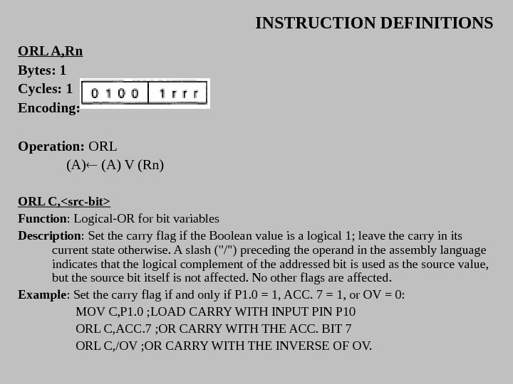
INSTRUCTION DEFINITIONS ORL A, Rn Bytes: 1 Cycles: 1 Encoding: Operation: ORL (A) V (Rn) ORL C, Function : Logical-OR for bit variables Description : Set the carry flag if the Boolean value is a logical 1; leave the carry in its current state otherwise. A slash («/») preceding the operand in the assembly language indicates that the logical complement of the addressed bit is used as the source value, but the source bit itself is not affected. No other flags are affected. Example : Set the carry flag if and only if P 1. 0 = 1, ACC. 7 = 1, or OV = 0: MOV C, P 1. 0 ; LOAD CARRY WITH INPUT PIN P 10 ORL C, ACC. 7 ; OR CARRY WITH THE ACC. BIT 7 ORL C, /OV ; OR CARRY WITH THE INVERSE OF OV.
INSTRUCTION DEFINITIONS ORL C, bit Bytes: 2 Cycles: 2 Encoding: Operation: ORL (C) V (bit) POP direct Function: Pop from stack. Description: The contents of the internal RAM location addressed by the Stack Pointer is read, and the Stack Pointer is decremented by one. The value read is then transferred to the directly addressed byte indicated. No flags are affected. Example: The Stack Pointer originally contains the value 32 H, and internal RAM locations 30 H through 32 H contain the values 20 H, 23 H, and Ol. H, respectively. The instruction sequence, POP DPH POP DPL will leave the Stack Pointer equal to the value 30 H and the Data Pointer set to 0123 H. At this point the instruction, POP SP will leave the Stack Pointer set to 20 H. Note that in this special case the Stack Pointer was decremented to 2 FH before being loaded with the value popped (20 H).
INSTRUCTION DEFINITIONS Bytes: 2 Cycles: 2 Encoding: Operation: POP (direct) (( SP )) (SP) (SP ) – 1 PUSH direct Function: Push onto stack Description: The Stack Pointer is incremented by one. The contents of the indicated variable is then copied into the internal RAM location addressed by the Stack Pointer. Otherwise no flags are affected. Example : On entering an interrupt routine the Stack Pointer contains 09 H. The Data Pointer holds the value 0123 H. The instruction sequence, PUSH DPL PUSH DPH will leave the Stack Pointer set to OBH and store 23 H and Ol. H in internal RAM locations OAH and OBH, respectively. Bytes: 2 Cycles:
INSTRUCTION DEFINITIONS Encoding: Operation: PUSH (SP) + 1 (( SP )) (direct) RETI Function: Return from interrupt Description: RETI pops the high- and low-order bytes of the PC successively from the stack, and restores the interrupt logic to accept additional interrupts at the same priority level as the one just processed. The Stack Pointer is left decremented by two. No other registers are affected; the PSW is not automatically restored to its pre-interrupt status. Program execution continues at the resulting address, which is generally the instruction immediately after the point at which the interrupt request was detected. If a lower- or same-level interrupt had been pending when the RETI instruction is executed, that one instruction will be executed before the pending interrupt is processed. Example: The Stack Pointer originally contains the value OBH. An interrupt was detected during the instruction ending at location 0122 H. Internal RAM locations OAH and OBH contain the values 23 H and Ol. H, respectively. The instruction, RETI will leave the Stack Pointer equal to 09 H and return program execution to location
INSTRUCTION DEFINITIONS Bytes: 1 Cycles: 2 Encoding: Operation: RETI (PC 15 — 8 ) (( SP )) (SP) — 1 (PC 7 — 0 ) (( SP )) (SP) —
INSTRUCTION DEFINITIONS RL A Function: Rotate Accumulator Left Description: The eight bits in the Accumulator are rotated one bit to the left. Bit 7 is rotated into the bit 0 position. No flags are affected. Example: The Accumulator holds the value 0 CSH ( 11000101 B). The instruction, RL A leaves the Accumulator holding the value 8 BH ( 10001011 B) with the carry unaffected. Bytes: 1 Cycles: 1 Encoding: Operation: RL (An + 1 ) (An) n = 0 – 6 (A 0 ) (A 7) RLC A Function: Rotate Accumulator Left through the Carry flag Description: The eight bits in the Accumulator and the carry flag are together rotated one bit to the left. Bit 7 moves into the carry flag; the original state of the carry flag moves into the bit 0 position. No other flags are affected. Example: The Accumulator holds the value 0 CSH (11000101 B), and the carry is zero. The instruction, RL
INSTRUCTION DEFINITIONS leaves the Accumulator holding the value 8 BH (10001010 B) with the carry set. Bytes : 1 Cycles : 1 Encoding: Operation: RLC (An + 1) (An) n = 0 — 6 (A 0) (C) (A 7) RR A Function: Rotate Accumulator Right Description: The eight bits in the Accumulator are rotated one bit to the right. Bit 0 is rotated into the bit 7 position. No flags are affected. Example: The Accumulator holds the value 0 C 5 H (11000101 B). The instruction, RR A leaves the Accumulator holding the value 0 E 2 H (11100010 B) with the carry unaffected. Bytes: 1 Cycles: 1 Encoding: Operation: RR (An) (An + 1) n = 0 — 6 (A 7) (A 0)
INSTRUCTION DEFINITIONS RRC A Function : Rotate Accumulator Right through Carry flag Description: The eight bits in the Accumulator and the carry flag are together rotated one bit to the right. Bit 0 moves into the carry flag; the original value of the carry flag moves into the bit 7 position. No other flags are affected. Example: The Accumulator holds the value 0 C 5 H (11000101 B), the carry is zero. The instruction, RRC A leaves the Accumulator holding the value 62 (01100010 B) with the carry set. Bytes : 1 Cycles : 1 Encoding: Operation: RRC (An) (An + 1) n = 0 — 6 (A 7) (C) (A 0)
INSTRUCTION DEFINITIONS SETB Function: Set Bit Description: SETB sets the indicated bit to one. SETB can operate on· the carry flag or any directly addressable bit. No other flags are affected. Example: The carry flag is cleared. Output Port 1 has been written with the value 34 H (00 l 10100 B). The instructions, SETB C SETB Pl. 0 will leave the carry flag set to 1 and change the data output on Port 1 to 35 H (00 l 10101 B). SETB C Bytes : 1 Cycles : 1 Encoding : Operation: SETB (C)
INSTRUCTION DEFINITIONS SETB bit Bytes : 2 Cycles : 1 Encoding : Operation: SETB (bit) 1 SJMP rel Function: Short Jump Description: Program control branches unconditionally to the address indicated. The branch destination is computed by adding the signed displacement in the second instruction byte to the PC, after incrementing the PC twice. Therefore, the range of destinations allowed is from 128 bytes preceding this instruction to 127 bytes following it. Example: The label «RELADR» is assigned to an instruction at program memory location 0123 H. The instruction, SJMP RELADR will assemble into location 0100 H. After the instruction is executed, the PC will contain the value 0123 H. ( Note : Under the above conditions the instruction following SJMP will be at l 02 H. Therefore, the displacement byte of the instruction will be the relative offset (0123 H 0102 H) = 21 H. Put another way, an SJMP with a displacement of 0 FEH would be a one-instruction infinite loop. )
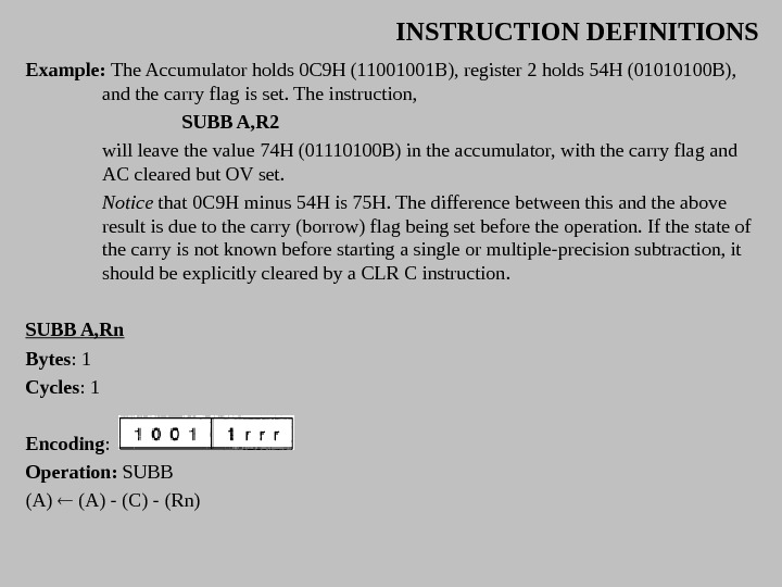
INSTRUCTION DEFINITIONS Bytes : 2 Cycles : 2 Encoding : Operation: SJMP (PC) + 2 (PC) + rel SUBB A, Function: Subtract with borrow Description: SUBB subtracts the indicated variable and the carry flag together from the Accumulator, leaving the result in the Accumulator. SUBB sets the carry (borrow) flag if a borrow is needed for bit 7, and clears C otherwise. (If C was set before executing a SUBB instruction, this indicates that a borrow was needed for the previous step in a multiple precision subtraction, so the carry is subtracted from the Accumulator along with the source operand. ) AC is set if a borrow is needed for bit 3, and cleared otherwise. OV is set if a borrow is needed into bit 6, but not into bit 7, or into bit 7, but not bit 6. When subtracting signed integers OV indicates a negative number produced when a negative value is subtracted from a positive value, or a positive result when a positive number is subtracted from a negative number. The source operand allows four addressing modes: register, direct, register-indirect, or immediate.
INSTRUCTION DEFINITIONS Example: The Accumulator holds 0 C 9 H (11001001 B), register 2 holds 54 H (01010100 B), and the carry flag is set. The instruction, SUBB A, R 2 will leave the value 74 H (01110100 B) in the accumulator, with the carry flag and AC cleared but OV set. Notice that 0 C 9 H minus 54 H is 75 H. The difference between this and the above result is due to the carry (borrow) flag being set before the operation. If the state of the carry is not known before starting a single or multiple-precision subtraction, it should be explicitly cleared by a CLR C instruction. SUBB A, Rn Bytes : 1 Cycles : 1 Encoding : Operation: SUBB (A) — (C) — (Rn)
INSTRUCTION DEFINITIONS SUBB A, direct Bytes : 2 Cycles : 1 Encoding : Operation: SUBB (A) — (C) — (direct) SUBB A, @Ri Bytes: 1 Cycles: 1 Encoding : Operation: SUBB (A) — (C) — ((Ri))
INSTRUCTION DEFINITIONS SUBB A, #data Bytes: 2 Cycles: 1 Encoding : Operation: SUBB (A) — (C) — #data SWAP A Function: Swap nibbles within the Accumulator Description: SWAP A interchanges the low- and high-order nibbles (four-bit fields) of the Accumulator (bits 3 -0 and bits 7 -4). The operation can also be thought of as a four-bit rotate instruction. No flags are affected. Example: The Accumulator holds the value 0 C 5 H (11000 l 0 l. B). The instruction, SWAP A leaves the Accumulator holding the value 5 CH (0 l 011100 B). Bytes: 1 Cycles: 1 Encoding: Operation: SWAP
INSTRUCTION DEFINITIONS XCH A, Function: Exchange Accumulator with byte variable Description: XCH loads the Accumulator with the contents of the indicated variable, at the same time writing the original Accumulator contents to the indicated variable. The source/destination operand can use register, direct, or register-indirect addressing. Example: R 0 contains the address 20 H. The Accumulator holds the value 3 FH (00111111 B). Internal RAM location 20 H holds the value 7 SH (01110101 B). The instruction, XCH A, @R 0 will leave RAM location 20 H holding the values 3 FH (00111111 B) and 75 H (0111010 l. B) in the accumulator. XCH A, Rn Bytes: 1 Cycles: 1 Encoding :
INSTRUCTION DEFINITIONS Operation: XCH A, direct Bytes: 2 Cycles: 1 Encoding : Operation: XCH A, @Ri Bytes: 1 Cycles: 1 Encoding : Operation: XCH
INSTRUCTION DEFINITIONS XCHD A, @Ri Function: Exchange Digit Description: XCHD exchanges the low-order nibble of the Accumulator (bits 3 -0), generally representing a hexadecimal or BCD digit, with that of the internal RAM location indirectly addressed by the specified register. The high-order nibbles (bits 7 -4) of each register are not affected. No flags are affected. Example : RO contains the address 20 H. The Accumulator holds the value 36 H (00 l 10110 B). Internal RAM location 20 H holds the value 75 H (0111010 l. B). The instruction, XCHD A, @R 0 will leave RAM location 20 H holding the value 76 H (011101 l 0 B) and 35 H (00110101 B) in the Accumulator. Bytes: 1 Cycles: 1 Encoding : Operation: XCH
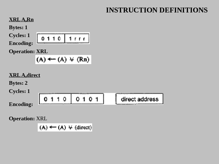
INSTRUCTION DEFINITIONS XRL , Function : Logical Exclusive-OR for byte variables Description: XRL performs the bitwise logical Exclusive-OR operation between the indicated variables, storing the results in the destination. No flags are affected. The two operands allow six addressing mode combinations. When the destination is the Accumulator, the source can use register, direct, register-indirect, or immediate addressing; when the destination is a direct address, the source can be the Accumulator or immediate data. ( Note : When this instruction is used to modify an output port, the value used as the original port data will be read from the output data latch, not the input pins. ) Example : If the Accumulator holds 0 C 3 H (1100001 IB) and register 0 holds 0 AAH (1010 B) then the instruction, XRL A, R 0 will leave the Accumulator holding the value 69 H (01101001 B). When the destination is a directly addressed byte, this instruction can complement combinations of bits in any RAM location or hardware register. The pattern of bits to be complemented is then determined by a mask byte, either a constant contained in the instruction or a variable computed in the Accumulator at run-time. The instruction, XRL PI, #00 ll 000 l. B will complement bits 5, 4, and 0 of output Port 1.
INSTRUCTION DEFINITIONS XRL A, Rn Bytes: 1 Cycles: 1 Encoding : Operation: XRL A, direct Bytes: 2 Cycles: 1 Encoding : Operation: XRL
INSTRUCTION DEFINITIONS XRL A, @Ri Bytes: 1 Cycles: 1 Encoding : Operation: XRL A, #data Bytes: 2 Cycles: 1 Encoding : Operation: XRL
INSTRUCTION DEFINITIONS XRL direct, A Bytes: 2 Cycles: 1 Encoding : Operation: XRL direct, #data Bytes: 3 Cycles: 2 Encoding : Operation: XRL