
ICACS-25 International Conference on «Atomic Collisions in Solids


icacs-25_international_conference_on.ppt
- Размер: 1.1 Mегабайта
- Количество слайдов: 26
Описание презентации ICACS-25 International Conference on «Atomic Collisions in Solids по слайдам
ICACS-25 International Conference on «Atomic Collisions in Solids “ Kyoto, JAPAN, 21 – 25 October, 2012 Hydrogen and Oxygen Trapping and Retention in Metals and Graphite Materials Irradiated in Plasma L. Begrambekov A. Ayrapetov, V. Ermakov, A. Kaplevsky, Ya. Sadovsky, P. Shigin National Research Nuclear University (MEPh. I), Moscow, Russia
Introduction The paper present s the early published and the new results of investigation of the hydrogen trapping under plasma irradiation. The materials of interest are — c arbon materials : carbon fiber composite – CFC and pyrolitic graphite – PG) , — metals: stainless steel having chromium enriched oxidized surface layer – SS and nicke l characterized by practically “clean” surface. The main attention is paid to the following questions: — Trapping and retention of the low energy plasma particles, — Trapping of hydrogen from the sorbed layers, — Hydrogen and oxygen trapping in the plasma with oxygen addition, — driving forces and mechanisms of the low energy particle hydrogen trapping.
Outline 1. The experimental devices and methods 2. The hydrogen and oxygen trapping and retention in CFC and PG — energy dependence and trapping mechanism, — flux (time) dependence, — temperature dependence, — hydrogen and oxygen trapping under irradiation in D 2 +O 2 plasma, — CD 4 formation and desorption. 3. The hydrogen and oxygen trapping and retention in SS and nickel — modification of working gas composition during plasma discharge, — energy dependence of trapping, — fluence dependence of trapping. 4. Conclusion
The experimental devices and methods
Thermal Desorptional Stand (TDS-2) • 1 — heated cathode, • 2 — sample heater, • 3 — sample, • 4 — anode, • 5 — mass-spectrometer, • 6 — plasma chamber, • 7 — plasma, • 8 — vacuum vessel, • 9 — to the vacuum pumping system. The main feature of the TDS-2 is the possibility to irradiate the samples in the gas discharge, and to make a thermal desorptional analysis of the samples in the same plasma chamber
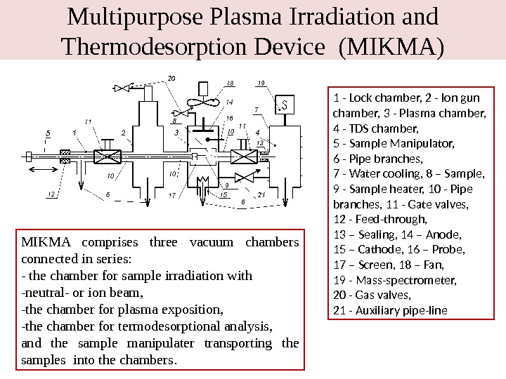
Multipurpose Plasma Irradiation and Thermodesorption Device (MIKMA) 1 — Lock chamber, 2 — Ion gun chamber, 3 — Plasma chamber, 4 — TDS chamber, 5 — Sample Manipulator, 6 — Pipe branches, 7 — Water cooling, 8 – Sample, 9 — Sample heater, 10 — Pipe branches, 11 — Gate valves, 12 — Feed-through, 13 – Sealing, 14 – Anode, 15 – Cathode, 16 – Probe, 17 – Screen, 18 – Fan, 19 — Mass-spectrometer, 20 — Gas valves, 21 — Auxiliary pipe-line. MIKMA comprises three vacuum chambers connected in series: — the chamber for sample irradiation with -neutral- or ion beam, -the chamber for plasma exposition, -the chamber for termodesorptional analysis, and the sample manipulater transporting the samples into the chambers.
Experimental parameters Т he residual gas pressure is about 1× 10 -3 Pa in TDS-2 and about 1× 10 -4 Pa in MIKMA. The working gas (D 2 ) pressure is about (1. 4 -1. 5)× 10 -1 Pa in both devices. The plasma composition is the D 2 ions (82– 85%), and the remaining part is D 1 and D 3 ions. The samples are 1) CFC N 11, 2) pyrolytic graphite PG 99, MPG-8 graphite 3) nickel, 4) stainless steel 12 Х 18 Н 10 Т (0. 12%C, 18%Cr, 10%Ni, ≤ 1%Ti) The CFC and PG samples are annealed at 1800 K and the metal samples at 1450 K. The PG samples were irradiated perpendicular to hexagonal layers. The samples were irradiated in the plasma and the gases retained in the samples during irradiation were measured by thermal desorptional spectrometry (TDS). M ass-spectrometer s were calibrated with the help of the calibrated leakage. The sample heating rate during TDS was equal to 5 K/s.
Hydrogen and oxygen trapping and retention in CFC and PG
Energy dependence of deuterium trapping in PG and CFC irradiated by the plasma ions and electrons 02004006008001000 0, 5 1, 0 1, 5 Desorption, x 1021 at m-2 CFC PG Ion energy, e. V 10 Electron energy, e. V 7, 6 x 10¹⁸ at m-2 j i = 10 20 at/m 2 s, Φ i = 5 10 23 at/m 2 s j e = 2 10 20 at/m 2 s, Φ e =10 24 at/m 2 s, T = 450 K 1. Deuterium is trapped even when energy of plasma ions approaches zero and under irradiation with plasma electrons. 2. The deuterium (hydrogen) contained molecules sorbed at the surface is the main source for trapping in carbon materials under low energy irradiation 3. The trapping of the low energy plasma ions and atoms is provided due to their potential energy with respect to the surface and occurs through inelastic collisions with the surface. 4. The active centers created by the impinging plasma particles initiate dissociation of the sorbed deuterium (hydrogen) contained molecules and trapping of the atoms. 5. Such type of trapping was named as “potential”. The trapping of fast particles due to their kinetic energy was labeled as “kinetic”Residual gas Retention (50 e. V irrad) Retention (500 e. V irrad) H/D 0. 007 0. 45 0.
Flux (time) dependence of deuterium trapping in CFC 02004006008001000 0, 5 1, 0 1, 5 2, 0 Electron energy, e. V 2, 2 x 10¹⁶ +/- 0, 6 x 10¹⁶ Retention, x 10 17 at/cm 2 Ion energy, e. V/at. CFC Deut. total (2 x 10¹⁹) CFC Deut. total (1 x 10²⁰) CFC D 2 2 x 10¹⁹ — D 2 1 x 10²⁰ 10 e. V j i = 10 20 at/m 2 s, Φ i = 5 10 23 at/m 2 s j e = 2 10 20 at/m 2 s, Φ e =10 24 at/m 2 s, T = 450 K 1. At equal fluencies deuterium trapping is higher, when ion flux density is smaller. (Irradiation time is higher). 2. Trapping of the atoms from the surface sorption through “potential” mechanism is time dependent process. It determines the time dependence of trapping as a whole. 3. T he atoms from the surface sorption trapped through “potential” mechanism can diffuse and occupy the traps in the ion stopping zone.
TDS spectra of D 2 desorbed from CFC irradiated by electrons and deuterium ions. 4006008001000120014001600 0, 5 1, 0 1, 5 2, 0 2, 5 Release rate, x 1015 at/sec/cm 2 Temperature, K CFC el. (1 x 10²⁰) CFC float (1 x 10²⁰) CFC 50 e. V/at (1 x 10²⁰) CFC 100 e. V/at (1 x 10²⁰) CFC 200 e. V/at (1 x 10²⁰) CFC 400 e. V/at (5 x 10¹⁹) CFC 500 e. V/at (1 x 10²⁰) CFC 800 e. V/at (1 x 10²⁰) CFC 1000 e. V/at (1 x 10²⁰) 1. The “potential” traps formed under low energy ion- and electron irradiation are similar and differ from the “kinetic” traps created under high energy ( E i >100 -200 e. V) ion irradiation. 2. “Kinetic” traps are created with ions having energy 3. In both cases some fraction of deuterium atoms penetrates behind the region directly influenced by ions and are trapped there. 4. The defects formed in the stopping zone diffuse out of it and promote the deuterium diffusion into the bulkj i = 10 20 at/m 2 s, Φ i = 5 10 23 at/m 2 s j e = 2 10 20 at/m 2 s, Φ e =10 24 at/m 2 s, T = 450 K
TDS spectra of D 2 desorbed from PG irradiated by electrons and deuterium ions. 4006008001000120014001600 0, 5 1, 0 1, 5 2, 0 2, 5 R elease rate, x 1015 at/sec/cm 2 Temperature, K Pyr. Gr. electr. Pyr. Gr. float Pyr. Gr. 50 e. V/at Pyr. Gr. 100 e. V/at Pyr. Gr. 200 e. V/at Pyr. Gr. 500 e. V/at Pyr. Gr. 800 e. V/at Pyr. Gr. 1000 e. V/at x 5 j i = 10 20 at/m 2 s, Φ i = 5 10 23 at/m 2 s j e = 2 10 20 at/m 2 s, Φ e =10 24 at/m 2 s T = 450 K
30060090012001500 0, 0 1, 0 x 10 -7 2, 0 x 10 -7 3, 0 x 10 -7 4, 0 x 10 -7 5, 0 x 10 -7 6, 0 x 10 -7 7, 0 x 10 -7 A. u. Temperature, K 25 e. V 50 e. V 100 e. V 200 e. V 300 e. V 400 e. V 500 e. V 600 e. V 700 e. V 900 e. V 1000 e. V Float 10 e. V Eion=0 Спектры десорбции водорода из графита МПГ-8 облученного ионами различных энергий и электронами. TDS spectra of H 2 desorbed from fine grain MPG-8 graphite irradiated by electrons and hydrogen ions. j i = 3. 5 10 20 at/m 2 s, Φ i = 6 10 23 at/m 2 s, j e = 10 20 at/m 2 s, Φ e = 10 24 at/m 2 s, T = 450 K
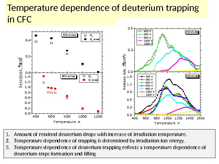
40060080010001200 0, 2 0, 4 0, 6 0, 8 1, 0 1, 2 1, 4 0, 0 0, 2 0, 4 Desorption, 1021 at/m 2 D 2 total 200 e. V/at D 2 total 800 e. V/at Temperature, KTemperature dependence of deuterium trapping in CFC 4006008001000120014001600 0, 3 0, 6 0, 9 1, 2 1, 5 0, 0 0, 3 0, 6 Release rate, 1019 at/m 2 s 400 K 600 K 800 K 1000 K 1200 K 200 e. V/at 800 e. V/at 500 K 560 K 600 K 650 K 800 K 1000 K 1200 K Temperature, K 1. A mount of retained deuterium drops with increase of irradiation temperature. 2. Temperature dependence of trapping is determined by irradiation energy. 3. Temperature dependence of deuterium trapping reflects a temperature dependence of deuterium traps formation and filling
Deuteromethane formation in CFC irradiated by deuterium ions and electrons 02004006008001000 0, 5 1, 0 1, 5 2, 0 2, 5 3, 0 Desorption, x 10 20 at m — 2 10 Electron energy, e. V Ion energy, e. V/at Thermal desorption of deuterium as CD 4 from CFC ( ) and PG ( ) j i = 10 20 at/m 2 s, Φ i = 5 10 23 at/m 2 s j e = 2 10 20 at/m 2 s, Φ e =10 24 at/m 2 s, T = 450 K 1. Deuteromethane is not formed during potential trapping in PG structure with high degree of perfection. 2. It is formed in both materials during kinetic trapping when radiation defects are created at the expense of ion kinetic energy.
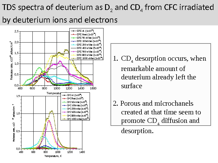
TDS spectra of deuterium as D 2 and CD 4 from CFC irradiated by deuterium ions and electrons 400 600 800 1000 1200 1400 16000, 51, 01, 52, 02, 5 Release rate, x 1015 at/sec/cm 2 Temperature, K CFC el. (1 x 10 20 ) CFC float (1 x 10 20 ) CFC 50 e. V/at (1 x 10 20 ) CFC 100 e. V/at (1 x 10 20 ) CFC 200 e. V/at (1 x 10 20 ) CFC 400 e. V/at (5 x 10 19 ) CFC 500 e. V/at (1 x 10 20 ) CFC 800 e. V/at (1 x 10 20 ) CFC 1000 e. V/at (1 x 10 20 ) 400600800100012001400 0, 5 1, 0 1, 5 Release rate, x 10 15 at/sec/cm 2 Temperature, K CFC el. (1 x 10²⁰) CFC float (1 x 10²⁰) CFC 50 e. V/at (1 x 10²⁰) CFC 100 e. V/at (1 x 10²⁰) CFC 200 e. V/at (1 x 10²⁰) CFC 500 e. V/at (1 x 10²⁰) CFC 800 e. V/at (1 x 10²⁰) CFC 1000 e. V/at (1 x 10²⁰) 1. CD 4 desorption occurs, when remarkable amount of deuterium already left the surface 2. Porous and microchanels created at that time seem to promote CD 4 diffusion and desorption.
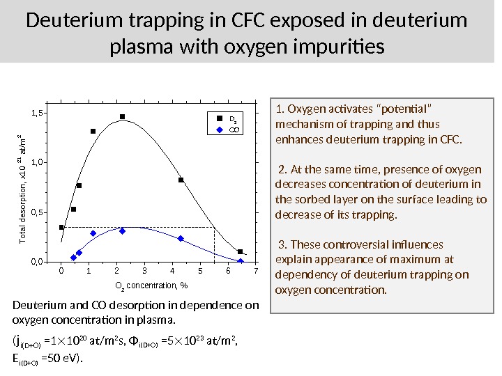
Deuterium trapping in CFC exposed in deuterium plasma with oxygen impurities 01234567 0, 0 0, 5 1, 0 1, 5 D 2 CO Total desorption, x 10 21 at/m 2 O 2 concentration, % Deuterium and CO desorption in dependence on oxygen concentration in plasma. ( j i(D+O) =1 10 20 at/m 2 s, Φ i(D+O) =5 10 23 at/m 2 , E i(D+O) =50 e. V). 1. Oxygen activates “potential” mechanism of trapping and thus enhances deuterium trapping in CFC. 2. At the same time, presence of oxygen decreases concentration of deuterium in the sorbed layer on the surface leading to decrease of its trapping. 3. These controversial influences explain appearance of maximum at dependency of deuterium trapping on oxygen concentration.
The hydrogen and oxygen trapping and retention in SS and nickel
Modification of working gas composition during plasma discharge Irradiation of the walls of the SS vacuum chamber with the deuterium atoms appeared in the working gas due to the D 2 molecule dissociation on the heated cathode or with plasma ions leads to: — the oxygen “disappearance” from the working gas — the D 2 O, HDO, H 2 O molecule formation and desorption , — the deuterium atom trapping. Deuterium and oxygen from working gas and hydrogen from the bulk of the vessel wall take part in the process. Gas composition in the vacuum chamber. 1 – residual gas 2 – Filling with the working gas (D 2 +2%O 2 ) 3 – The tungsten cathode is heated 4 – The plasma is switched Total hydrogen release from the wall is ≈7× 10 17 at/cm 3 → Δ (H/Me)= 7× 10 —
The possible D-atom/ion induced exothermic reactions on the SS surface resulting in the “waters” molecule formation and deuterium trapping , , , Cr 2 O 3 + D = OD + Cr 2 O 2 OD+D 2 =D 2 O↑+ D OD+H diff =HDO↑ OD+D=D 2 O↑ Cr 2 O 2 +H diff =Cr 2 O 3 +OH OH+H diff =H 2 O ↑ OH+D=HDO ↑ OH+D 2 =HDO+ D trapping trapping …… 1. Deuterium atom appeared on the surface could be trapped or start the new cycle of the reactions. 2. The reactions can have the chain character under the proper conditions. 3. The amount of the diffused from the bulk hydrogen atoms during the single reaction cycle (3) is smaller than amount of the trapped deuterium atoms (1 -2). Thus the reactions leads to the vessel wall outgasing.
The deuterium, hydrogen and oxygen trapping in the annealed SS ( P w. g = (1. 4 -1. 5)× 10 -1 Pa, Exposition =40 min, E i =100 e. V/at, Φ =5 × 10 19 ат/м 2 , T= 420 К ) Total desorption Working gas (D 2 +2%O 2 ) Working gas, heated cathode Plasma E i =100 e. V/at H (10 19 at/m 2 ) 9. 6 31 27. 0 D (10 19 at/m 2 ) 0. 9 12 25. 0 H/D 10. 7 2. 6 1. 08 O (10 19 at/m 2 ) 1. 8 6. 4 8. 0 The presumable fraction of hydrogen and oxygen and evidently the significant fraction of deuterium occur from the water molecules sorbed on the surface with bombarding atoms stimulating this process. Modification of working gas composition and enhanced hydrogen isotope and oxygen trapping are the results of the various “potential” processes on the SS surface. One can believe that the comparably high life time of the active centers created by plasma irradiation on the oxidized SS surface is the cause of the high efficiency of the “potential” processes on the SS surface.
Energy dependence on deuterium trapping in SS and nickel irradiated by the plasma ions Under low energy irradiation the main fraction of deuterium is bonded with chromium within the surface oxide layer even though its concentration in the layer ≤ 17 -20%. As the ion energy increases the deuterium atoms penetrate and are trapped in the bulk. The ability of the bulk regions to trap deuterium seems to be much lower than that of the oxide layer, and there is no a significant difference between probabilities of trapping in “chromium” or “iron” traps. In case of a nickel sample having no oxide layer on the surface, and the deuterium trapping constantly increases within the ion energy. 400 600 800 1000 1200 1400036912151821 D 2 desorbtion rate, m ol/m 2 s x 1017 Temperature, K 20 e. V/at ion energy 30 e. V/at ion energy 50 e. V/at ion energy 100 e. V/at ion energy 300 e. V/at ion energy 500 e. V/at ion energy 700 e. V/at ion energy 0100200300400500600700 1 2 3 4 5 6 stainless steel nickel D atom s desorbtion, at/m 2 x 10²⁰ Energy of D ions, e. V/at Irradiation of: Φ =5 x 10 22 at/m 2 j i = 2 х10 19 at/m 2 s
Fluence dependence on deuterium and oxygen trapping in SS and nickel 020406080100120 0, 1 0, 2 0, 3 0, 4 0, 5 0, 6 0, 7 0, 8 0246810121416 D atom s desorbtion, at/m 2 x 10²⁰ Irradiation time, min Deuterium Oxygen Ni 020406080100120 0, 5 1, 0 1, 5 2, 0 2, 5 3, 0 3, 5 4, 0 4, 5 5, 0 0246810121416 D atom s desorbtion, at/m 2 x 10²⁰ Irradiation time, min Deuterium Oxygen SS Irradiation dose , х 10 22 ат/м 2 E i =100 e. V, j i = 2 х10 19 ат/м 2 сек Irradiation dose , х 10 22 ат/м 2 The linear increase of the deuterium trapping in the SS within the ion fluence reports that the oxide layer acts as a barrier for the implanted deuterium atoms. It provides the constant increase of the deuterium concentration in the ion stopping zone and the constant rate of the deuterium diffusion into the bulk. The increase of the deuterium trapping in nickel slows down after the ion stopping zone saturation, because the diffusion of the implanted atoms into the bulk is very low
Conclusion Carbon materials. CFC and PG trap deuterium even when the energy of impinging plasma particles approached zero and under electron irradiation. Under irradiation at equal fluences the deuterium trapping is higher when ion current density is smaller. Hydrogen of the residual gas comprises the remarkable fraction of the whole trapping. The trapping of the low energy ions and atoms is provided at the expense of their potential energy with respect to the surface and occurs through the inelastic interactions with the surface. The active surface centers created by the both low- and high energy plasma particles initiate dissociation of the sorbed deuterium (hydrogen) containing molecules and the trapping of the atoms. Such trapping was named as “potential”. The trapping of fast particles due to their kinetic energy was labeled as “kinetic”. Time dependence of the trapping is caused by the “ potential ” trapping of atoms from the layer of surface sorption. The atoms penetrating surface through potential mechanism can fill the traps formed by the fast ions in the stopping zone. The oxygen irradiation activates “ potential ” trapping.
Conclusion SS and Nickel. Irradiation of the walls of the SS vessel with the neutrals or/and ions of (D 2 +O 2 ) plasma initiate D 2 O, HDO, H 2 O molecule formation. Hydrogen from the vessel wall participates in the process. The low energy deuterium and hydrogen atoms trapped in the SS are mainly bonded with chromium inside the surface oxide layer. High energy particles penetrate into- and are trapped in the bulk. The oxide layer hampers the release of the implanted deuterium from SS. It provides the constant increase of the deuterium concentration in the ion stopping zone and the constant rate of its diffusion into the bulk. Modification of working gas composition and enhancement of the hydrogen isotope and oxygen trapping are the results of the various “potential” processes on the SS surface. One can believe that the cause of the high efficiency of the “potential” processes on the destructed surface of carbon materials and on oxidized SS surface is the comparably high life time of the surface active centers created by plasma irradiation.
Thank you for your attention!