
Hotel Room Intelligent System applications SMART-HDL


- Размер: 5.7 Mегабайта
- Количество слайдов: 45
Описание презентации Hotel Room Intelligent System applications SMART-HDL по слайдам
Hotel Room Intelligent System applications SMART-HDL
1. System Composition
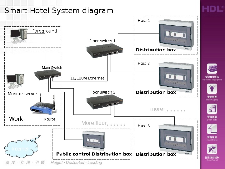
Main Switch Route. Work. Monitor server Internet. Smart-Hotel System diagram Floor switch 1 Distribution box Host 1 Floor switch 2 Foreground 10/100 M Ethernet Public control Distribution box Host 2 Distribution box Host N ……more ……More floor
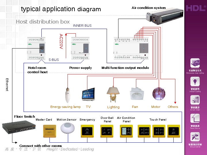
typical application diagram Touch Panel. Master Card Door Bell Panel. Emergency. AC 220 VPower supply Multi function output module. Hotel room control host INNER BUS Energy-saving lamp TV Lighting Fan Connect with other rooms. Floor Switch Ethernet Motor Others. Host distribution box Motion Sensor Air Condition Panel Air condition system S-BUS
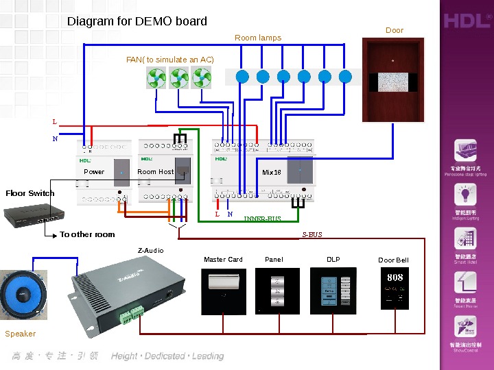
Diagram for DEMO board L N INNER-BUS S-BUS Master Card Panel DLPZ-Audio Mix 18 Room lamps FAN( to simulate an AC) Door Speaker Door Bell. Room Host Power L NFloor Switch To other room
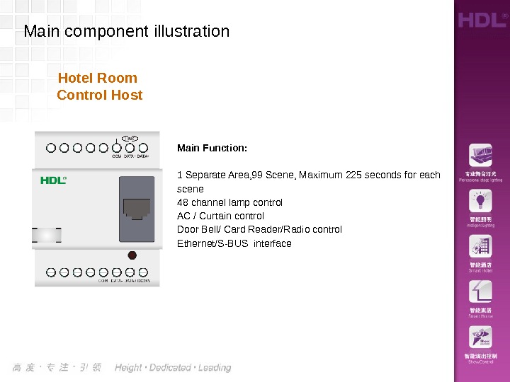
Main Function: 1 Separate Area, 99 Scene, Maximum 225 seconds for each scene 48 channel lamp control AC / Curtain control Door Bell/ Card Reader/Radio control Ethernet/S-BUS interface Hotel Room Control Host. Main component illustration
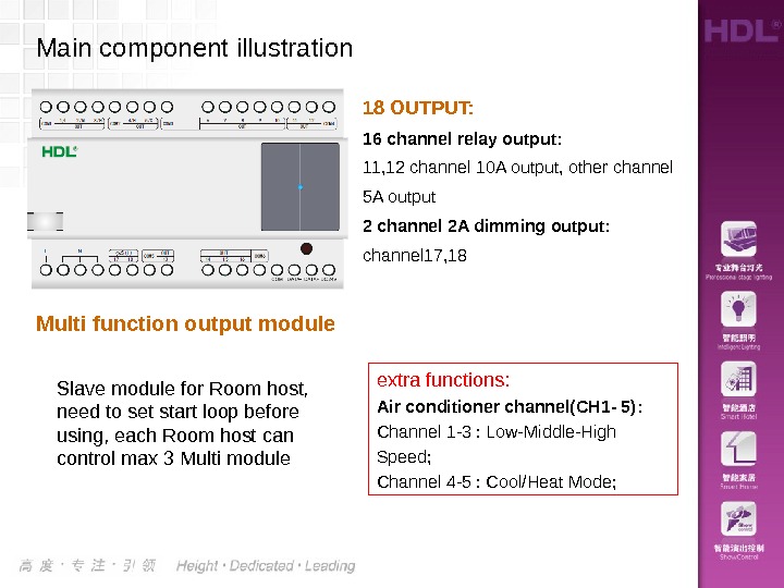
18 OUTPUT: 16 channel relay output: 11, 12 channel 10 A output, other channel 5 A output 2 channel 2 A dimming output: channel 17, 18 extra functions: Air conditioner channel(CH 1 — 5): Channel 1 -3 : Low-Middle-High Speed; Channel 4 -5 : Cool/Heat Mode; Main component illustration Multi function output module Slave module for Room host, need to set start loop before using, each Room host can control max 3 Multi module
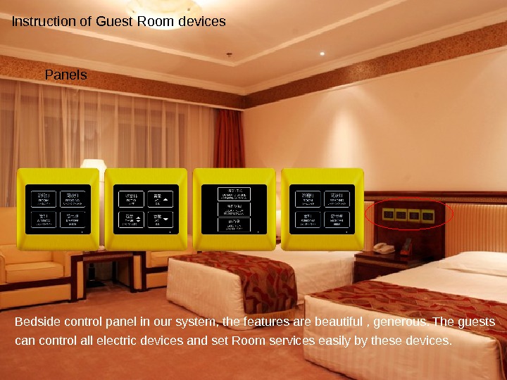
Bedside control panel in our system, the features are beautiful , generous. The guests can control all electric devices and set Room services easily by these devices. Instruction of Guest Room devices Panels
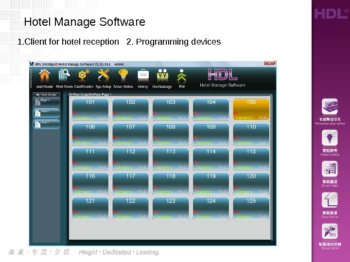
1. Client for hotel reception 2. Programming devices Hotel Manage Software
Questions and idea of our system ?
2. system application
• 1 Add a Room • 2 Issue a Room card • 3 Open the door with a room card • 4 Insert a card for power • 5 panel application : Lamp/AC control • 6 panel application : Set service status clear-up/l aundry /DND • 7 panel application: Playing music Application examples
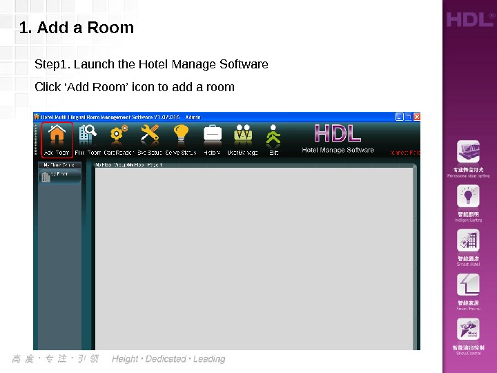
1. Add a Room Step 1. Launch the Hotel Manage Software Click ‘Add Room’ icon to add a room
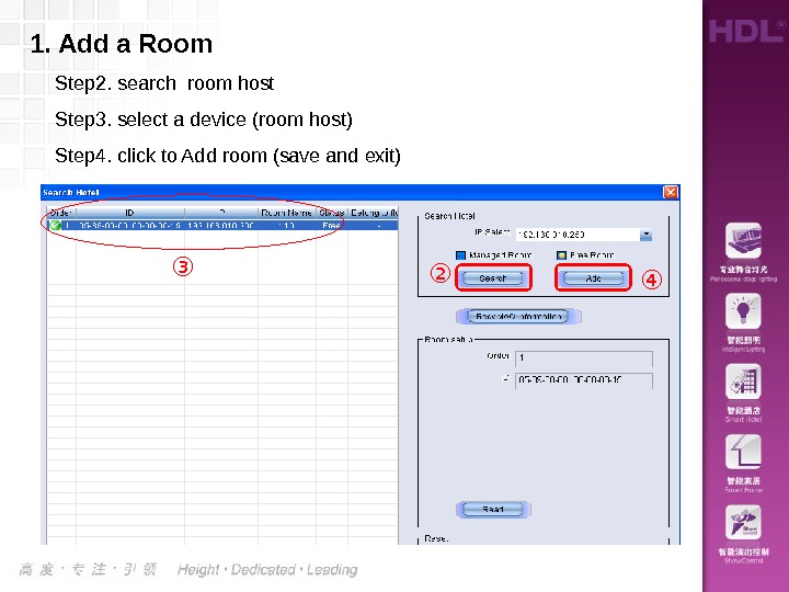
1. Add a Room Step 2. search room host Step 3. select a device (room host) Step 4. click to Add room (save and exit) ③ ② ④
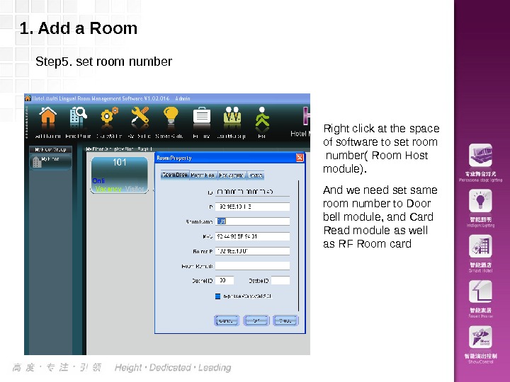
1. Add a Room Step 5. set room number Right click at the space of software to set room number( Room Host module). And we need set same room number to Door bell module, and Card Read module as well as RF Room card
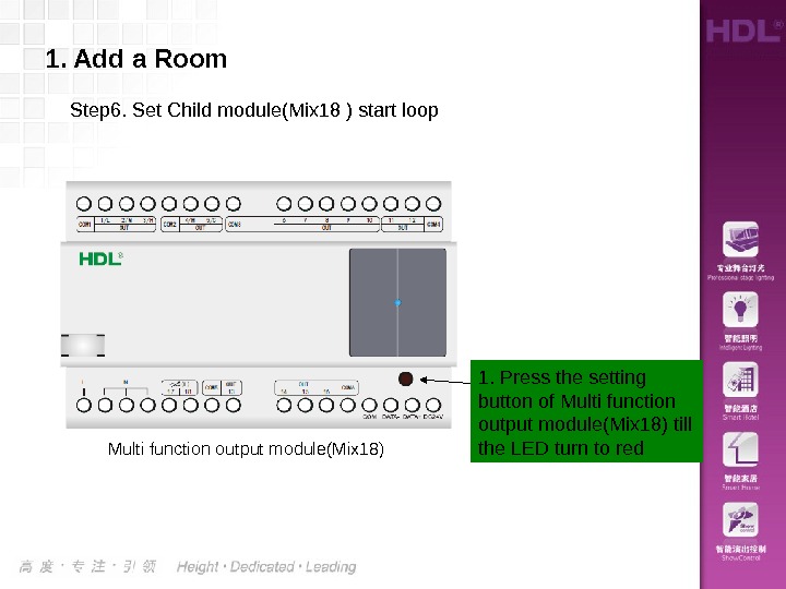
1. Add a Room Step 6. Set Child module(Mix 18 ) start loop 1. Press the setting button of Multi function output module(Mix 18) till the LED turn to red Multi function output module(Mix 18)
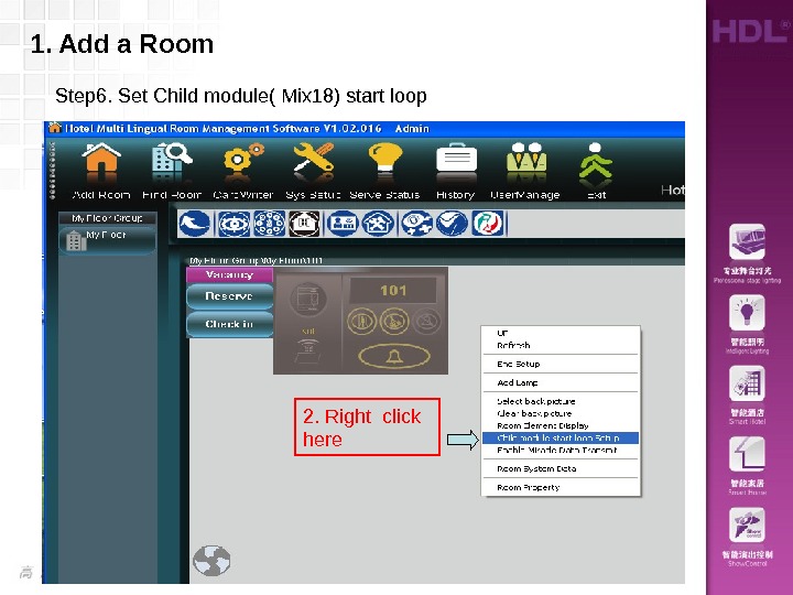
1. Add a Room Step 6. Set Child module( Mix 18) start loop 2. Right click here
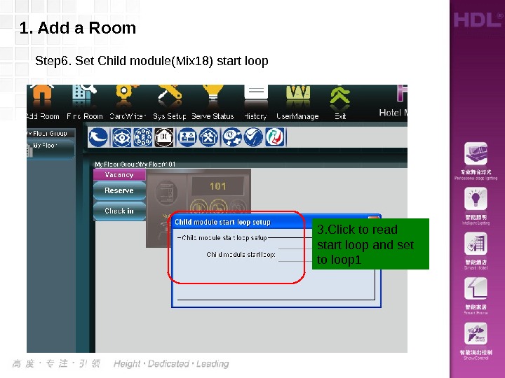
1. Add a Room Step 6. Set Child module(Mix 18) start loop 3. Click to read start loop and set to loop
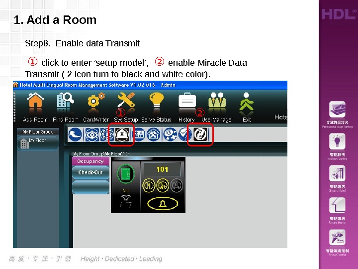
1. Add a Room Step 8. Enable data Transmit ① click to enter ’setup model’, ② enable Miracle Data Transmit ( 2 icon turn to black and white color). ① ②
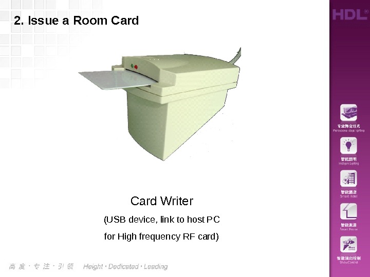
Card Writer (USB device, link to host PC for High frequency RF card)2. Issue a Room Card
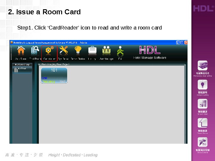
2. Issue a Room Card Step 1. Click ‘Card. Reader’ icon to read and write a room card
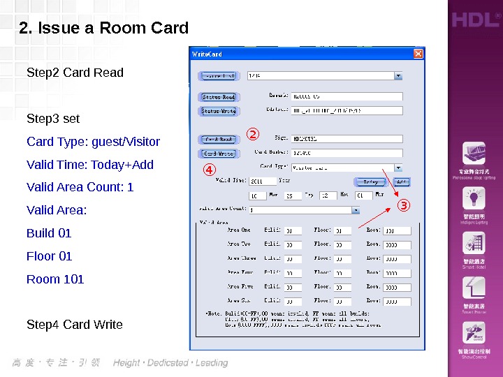
2. Issue a Room Card Step 2 Card Read Step 3 set Card Type: guest/Visitor Valid Time: Today+Add Valid Area Count: 1 Valid Area: Build 01 Floor 01 Room 101 Step 4 Card Write ② ③④
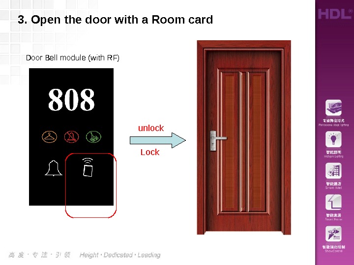
3. Open the door with a Room card Lockunlock. Door Bell module (with RF)
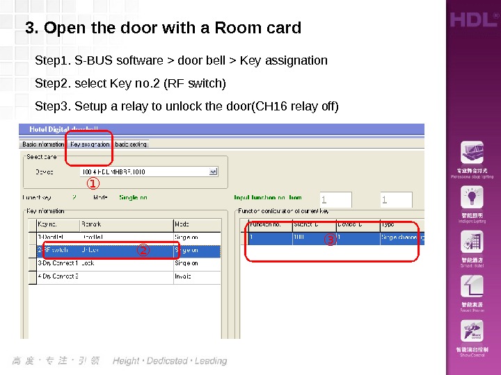
3. Open the door with a Room card ① ② ③Step 1. S-BUS software > door bell > Key assignation Step 2. select Key no. 2 (RF switch) Step 3. Setup a relay to unlock the door(CH 16 relay off)
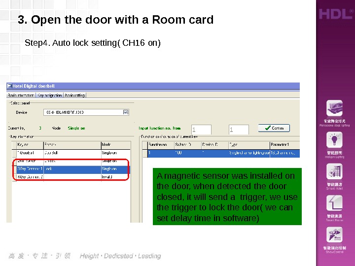
3. Open the door with a Room card Step 4. Auto lock setting( CH 16 on) A magnetic sensor was installed on the door, when detected the door closed, it will send a trigger, we use the trigger to lock the door( we can set delay time in software)
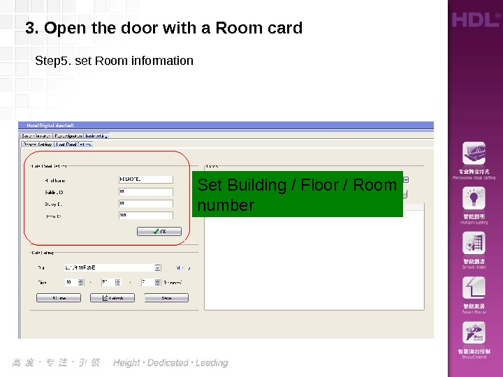
Step 5. set Room information 3. Open the door with a Room card Set Building / Floor / Room number
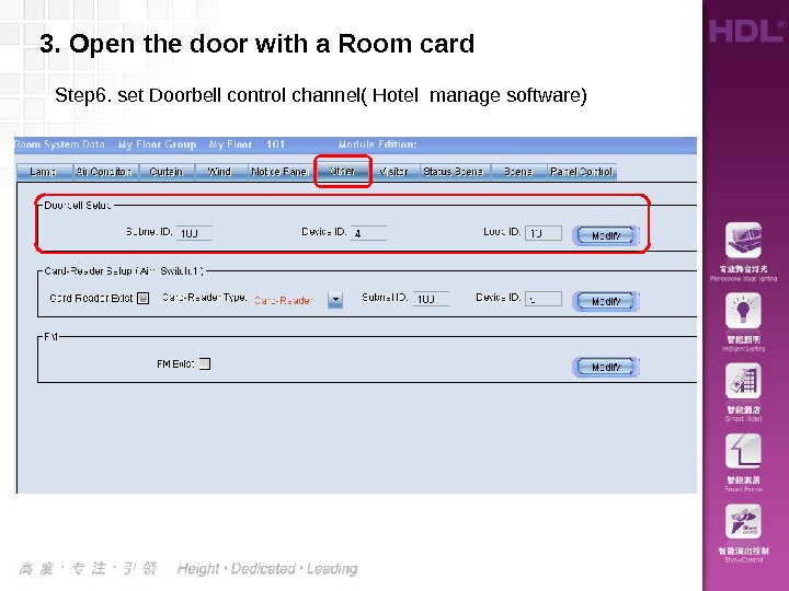
Step 6. set Doorbell control channel( Hotel manage software)3. Open the door with a Room card
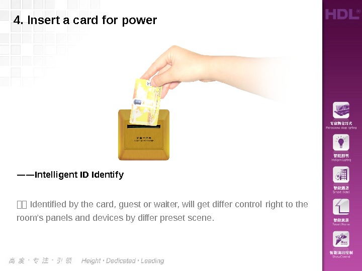
4. Insert a card for power —— Intelligent ID Identify :: Identified by the card, guest or waiter, will get differ control right to the room’s panels and devices by differ preset scene.
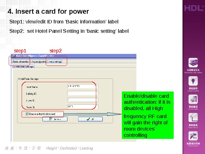
4. Insert a card for power Step 1: view/edit ID from ‘Basic information’ label Step 2: set Hotel Panel Setting in ‘basic setting’ label Enable/disable card authentication: if it is disabled, all High frequency RF card will gain the right of room devices’ controllingstep 1 step
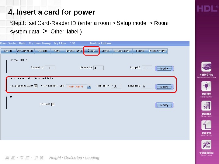
4. Insert a card for power Step 3: set Card-Reader ID (enter a room > Setup mode > Room system data > ’Other’ label )
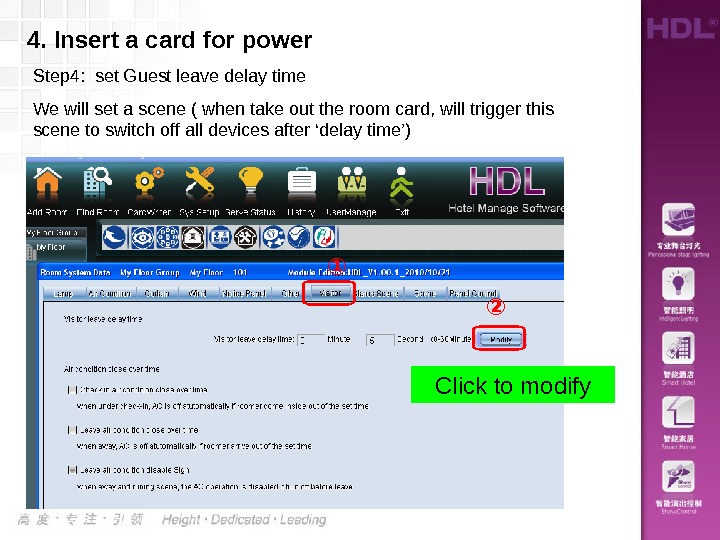
Step 4: set Guest leave delay time We will set a scene ( when take out the room card, will trigger this scene to switch off all devices after ‘delay time’) 4. Insert a card for power Click to modify① ②
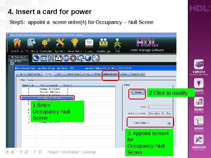
Step 5: appoint a scene order(4) for Occupancy – Null Scene 4. Insert a card for power 1. Selce Occupancy-Null Scene 2. Click to modify 3. Appoint scene 4 for Occupancy-Null Scene
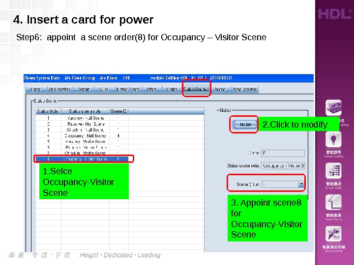
4. Insert a card for power Step 6: appoint a scene order(8) for Occupancy – Visitor Scene 1. Selce Occupancy-Visitor Scene 2. Click to modify 3. Appoint scene 8 for Occupancy-Visitor Scene
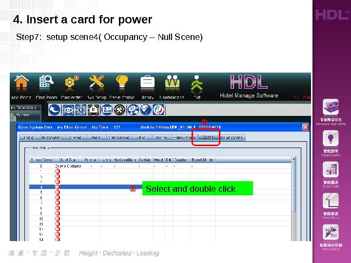
4. Insert a card for power Step 7: setup scene 4( Occupancy – Null Scene) ② ① Select and double click
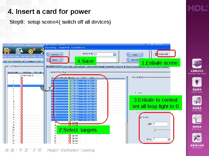
2. Select targets 3. Enbale to control set all loop light to 0 1. Enbale scene 4. Insert a card for power Step 8: setup scene 4( switch off all devices) 4. Save
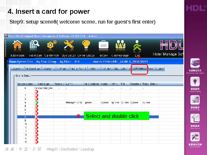
4. Insert a card for power Step 9: setup scene 8( welcome scene, run for guest’s first enter) ② ① Select and double click
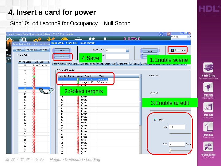
4. Insert a card for power Step 10: edit scene 8 for Occupancy – Null Scene 2. Select targets 3. Enable to edit 1. Enable scene 4. Save
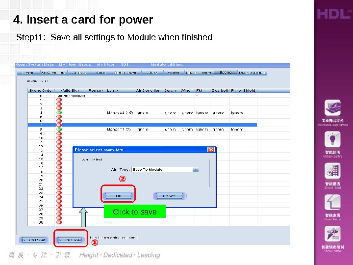
4. Insert a card for power Step 11: Save all settings to Module when finished Click to save ② ①
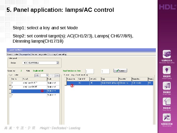
5. Panel application: lamps/AC control ① ②Step 1: select a key and set Mode Step 2: set control target(s): AC(CH 1/2/3), Lamps( CH 6/7/8/9), Dimming lamps(CH 17/18)
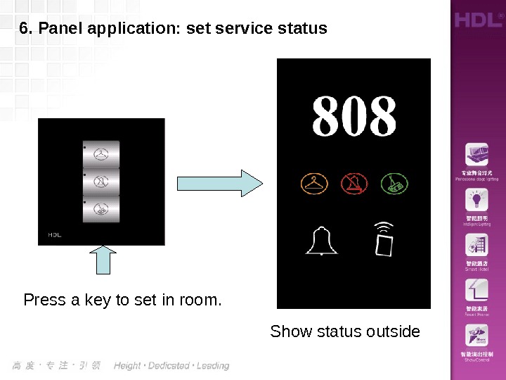
6. Panel application: set service status Press a key to set in room. Show status outside
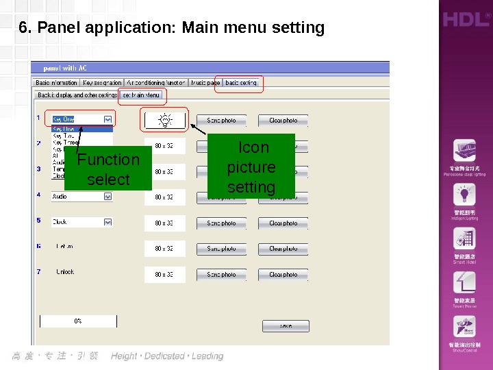
6. Panel application: Main menu setting Function select Icon picture setting
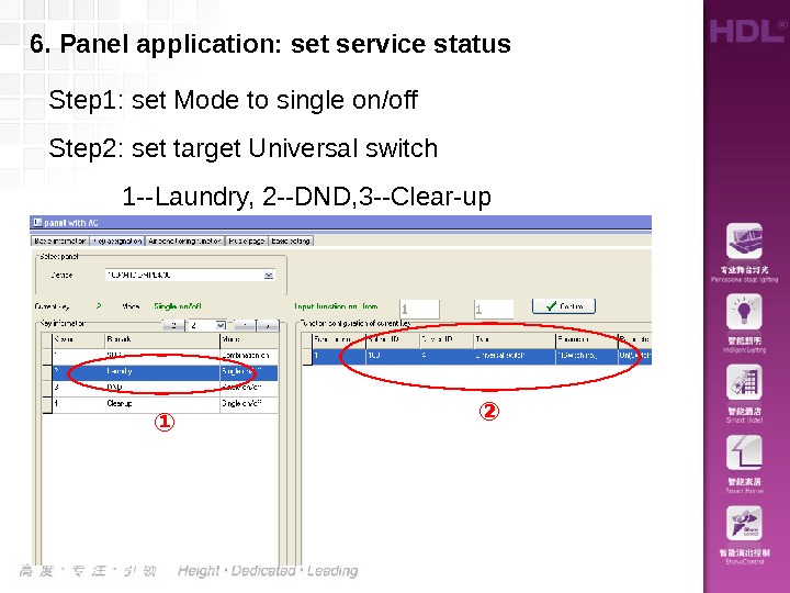
6. Panel application: set service status Step 1: set Mode to single on/off Step 2: set target Universal switch 1 —Laundry, 2 —DND, 3 —Clear-up ① ②
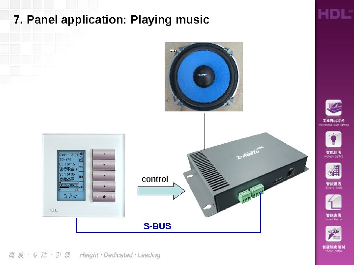
7. Panel application: Playing music control S-BUS
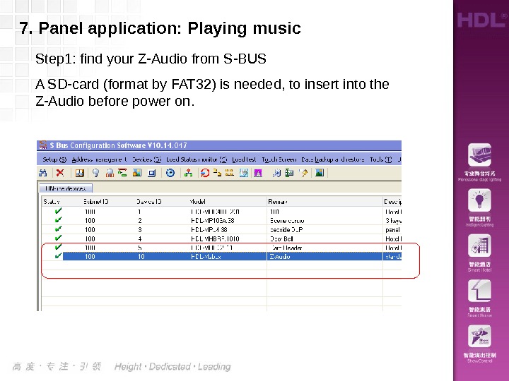
Step 1: find your Z-Audio from S-BUS A SD-card (format by FAT 32) is needed, to insert into the Z-Audio before power on. 7. Panel application: Playing music
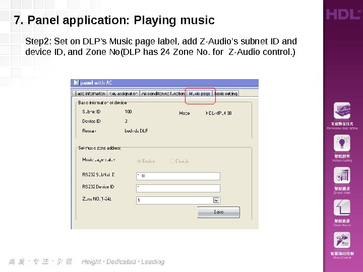
Step 2: Set on DLP’s Music page label, add Z-Audio’s subnet ID and device ID, and Zone No(DLP has 24 Zone No. for Z-Audio control. )7. Panel application: Playing music