
GROUP B — AIRPLANE GENERAL TRAINING USE ONLY


- Размер: 21 Mегабайта
- Количество слайдов: 64
Описание презентации GROUP B — AIRPLANE GENERAL TRAINING USE ONLY по слайдам
GROUP B — AIRPLANE GENERAL TRAINING USE ONLY Airplane General B-01 ATA-chapter 03 / GENERAL DESCRIPTION ATA-chapter 04 / AIRWORTHINESS LIMITATION ATA-chapter 05 / TIME LIMITS/MAINT. CHECKS ATA-chapter 06 / DIMENSIONS & AREAS ATA-chapter 07 / LIFTING & SHORING ATA-chapter 08 / WEIGHING & LEVELLING ATA-chapter 09 / TOWING & TAXIING ATA-chapter 10 / PARKING & MOORING ATA-chapter 11 / PLACARDS & MARKINGS ATA-chapter 12 / SERVICING DA 40 Series (Austro Engine) Issue: July
TRAINING USE ONLYATA 03 – GENERAL DESCRIPTION Airplane General B-02 DA 40 Series (Austro Engine) Issue: July
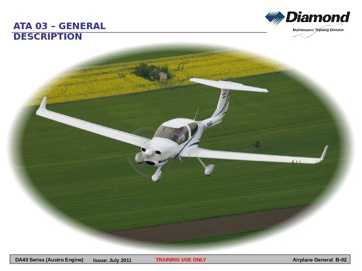
TRAINING USE ONLYATA 03 – GENERAL DESCRIPTION Airplane General B-03 General Diamond Aircraft Industries Gmb. H, N. A. Otto-Straße 5, A-2700 Wiener Neustadt, Austria, is the manufacturer of the DA 40 NG airplane. Description The DA 40 NG is a single-engine, four seat, low-wing monoplane. It has a cantilever wing and a ‘T’ tail. The airplane structure is fiber-reinforced plastic composite. This gives a very strong but light structure. The semi-monocoque fuselage is a glass-fiber reinforced-plastic (GFRP) shell with GFRP bulkheads and stiffeners. Uni-directional carbon fiber bands give extra strength and stiffness in many areas. Left and right half-shells bond together with a center section to make the fuselage. The center section makes the bottom of the cockpit. It has the main bulkheads which connect to the spars in each wing. The vertical stabilizer has two GFRP half-shells that are part of the fuselage shells. The cantilever wing is a semi-monocoque structure. Each wing has two I-shaped spars with webs made form GFRP/rigid foam sandwich and caps made from CFRP bands. Each wing has top and bottom shells made of CFRP/GFRP/rigid foam sandwich which bond to the spars. GFRP ribs and webs bond to the spars and shells to complete the structure. The wings attach to the fuselage center section. Each wing has two stump-spars. Four large bolts attach each wing to the fuselage main bulkheads. Standard ailerons and electrically operated flaps attach to the trailing edge of the wing. The horizontal stabilizer is a semi-monocoque structure. It has top and bottom shells made of GFRP. The shells bond to GFRP spars and ribs. The trailing edge has a conventional elevator and a trim tab. The one-piece canopy has a large quantity of wrap-around glazing. This gives a good all-round view from the cockpit. A glazed rear passenger door gives access to the rear seats from the left side of the airplane. A polyurethane paint finish protects the outside skin from ultraviolet rays and humidity. The fixed tricycle landing gear has fairings attached to each leg. The main legs attach to the fuselage center-section. The nose leg attaches to the forward fuselage. Each main wheel has a disc brake on the inside. Hydraulic pressure operates each disc brake. The flight control system uses conventional ailerons, elevator and rudder. The DA 40 NG has two control sticks and two rudder pedal assemblies to operate the primary flight-controls. DA 40 Series (Austro Engine) Issue: July
TRAINING USE ONLYATA 03 – GENERAL DESCRIPTION Airplane General B-04 Push-pull rods operate the ailerons and elevator. Cables operate the rudder. An electric motor operates the wing flaps. A hand wheel and Bowden cable operate the elevator trim. The DA 40 NG is powered by an Austro Engine E 4 -A liquid-cooled, in-line four-stroke four cylinder engine with double overhead camshaft (DOHC) with four valves per cylinder. The valves are actuated by the cam follower. The direct fuel injection is realized by means of a common rail technique and the engine is charged by a turbo-charger in combination with an intercooler. The propeller is activated by an integrated gearbox with an integral torsional vibration damper. All engine components are controlled by an EECU system. The airplane has an aluminum fuel tank in each wing. Each tank consists of several chambers. The fuel tanks are inboard between the spars. The tank assemblies have fuel fillers at or near the outboard end. Flexible hoses connect the tanks to a fuel selector and shut-off valve under the cockpit floor. An electrically driven pump supplies fuel to the engine. The tanks have fuel quantity probes which operate the cockpit indicating systems. The airplane has two sources of electrical power. A 28 Volt battery supplies power when the engine is not running. An alternator provides power when the engine is running. Switches and circuit breakers control all electrical devices. A starter key controls the engine starter motor. It also controls the serves as ELECTRIC MASTER key switch. The DA 40 NG has a full range of flight instruments. These include Pitot/static instruments to show airspeed and altitude, as well as electrically driven instruments to show direction. Most indications are shown on the G 1000 and only the backup instruments are installed on the instrument panel. The airplane has all the usual engine instruments, except a load indication instead of a manifold pressure indication. The airplane also has radio and navigation aids installed. DA 40 Series (Austro Engine) Issue: July
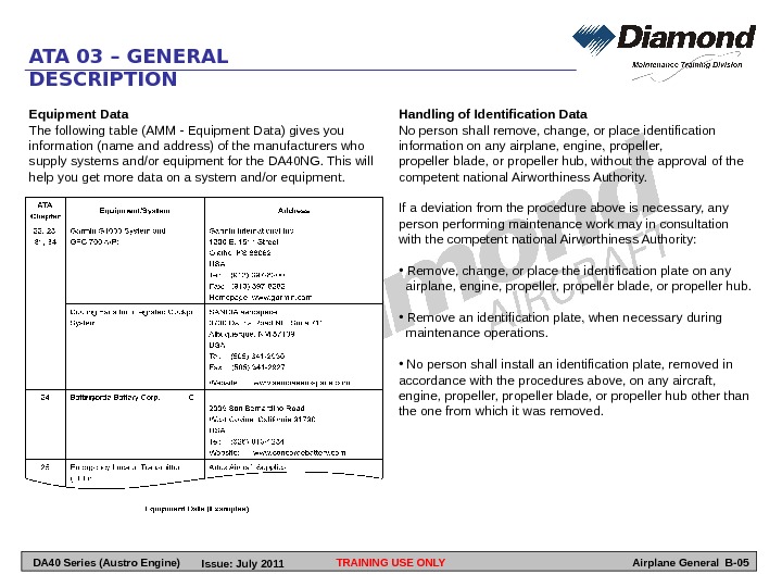
TRAINING USE ONLYATA 03 – GENERAL DESCRIPTION Airplane General B-05 Equipment Data The following table (AMM — Equipment Data) gives you information (name and address) of the manufacturers who supply systems and/or equipment for the DA 40 NG. This will help you get more data on a system and/or equipment. Handling of Identification Data No person shall remove, change, or place identification information on any airplane, engine, propeller blade, or propeller hub, without the approval of the competent national Airworthiness Authority. If a deviation from the procedure above is necessary, any person performing maintenance work may in consultation with the competent national Airworthiness Authority: • Remove, change, or place the identification plate on any airplane, engine, propeller blade, or propeller hub. • Remove an identification plate, when necessary during maintenance operations. • No person shall install an identification plate, removed in accordance with the procedures above, on any aircraft, engine, propeller blade, or propeller hub other than the one from which it was removed. DA 40 Series (Austro Engine) Issue: July
TRAINING USE ONLYATA 03 – GENERAL DESCRIPTION Airplane General B-06 LEFT BLANK DA 40 Series (Austro Engine) Issue: July
TRAINING USE ONLYATA 04 – AIRWORTHINESS LIMITATIONS Airplane General B-07 DA 40 Series (Austro Engine) Issue: July
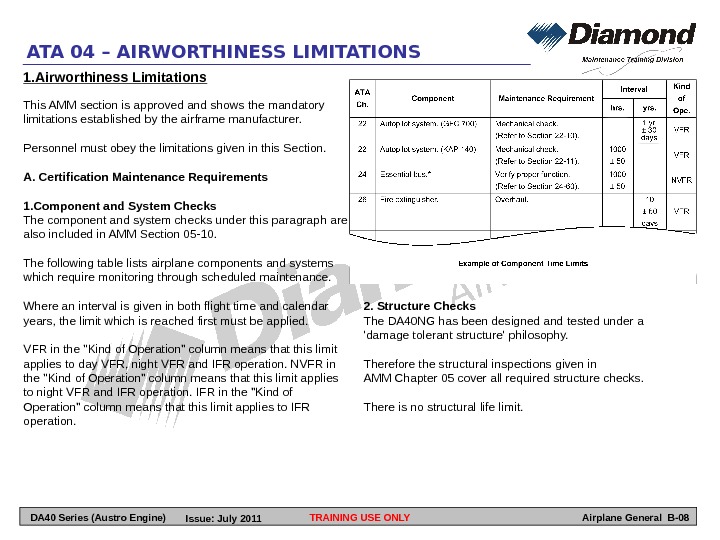
TRAINING USE ONLYATA 04 – AIRWORTHINESS LIMITATIONS Airplane General B-081. Airworthiness Limitations This AMM section is approved and shows the mandatory limitations established by the airframe manufacturer. Personnel must obey the limitations given in this Section. A. Certification Maintenance Requirements 1. Component and System Checks The component and system checks under this paragraph are also included in AMM Section 05 -10. The following table lists airplane components and systems which require monitoring through scheduled maintenance. Where an interval is given in both flight time and calendar years, the limit which is reached first must be applied. VFR in the «Kind of Operation» column means that this limit applies to day VFR, night VFR and IFR operation. NVFR in the «Kind of Operation» column means that this limit applies to night VFR and IFR operation. IFR in the «Kind of Operation» column means that this limit applies to IFR operation. 2. Structure Checks The DA 40 NG has been designed and tested under a ‘damage tolerant structure’ philosophy. Therefore the structural inspections given in AMM Chapter 05 cover all required structure checks. There is no structural life limit. DA 40 Series (Austro Engine) Issue: July
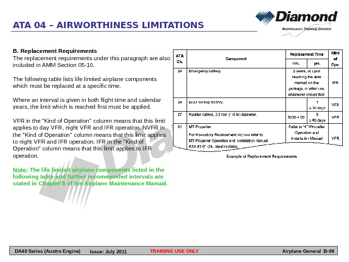
TRAINING USE ONLYATA 04 – AIRWORTHINESS LIMITATIONS Airplane General B-09 B. Replacement Requirements The replacement requirements under this paragraph are also included in AMM Section 05 -10. The following table lists life limited airplane components which must be replaced at a specific time. Where an interval is given in both flight time and calendar years, the limit which is reached first must be applied. VFR in the «Kind of Operation» column means that this limit applies to day VFR, night VFR and IFR operation. NVFR in the «Kind of Operation» column means that this limit applies to night VFR and IFR operation. IFR in the «Kind of Operation» column means that this limit applies to IFR operation. Note: The life limited airplane components listed in the following table and further recommended intervals are stated in Chapter 5 of the Airplane Maintenance Manual. DA 40 Series (Austro Engine) Issue: July
TRAINING USE ONLYATA 04 – AIRWORTHINESS LIMITATIONS Airplane General B-10 C. Colour of Airframe It is mandatory to paint the DA 40 NG white as described in AMM chapter 51. This will prevent the temperature of the structure from becoming too high. Examples of approves shades are: -RAL 9016 -Mercedes DB 147 — BMW 218 — Volvo XG 28 — Volvo BC 76 — Saab 5 AC 6 — Alfa Romeo 230 Before painting the DA 40 NG in a different shade the manufacturer must be contacted. Only certain areas which are defined in chapter 51 of the AMM (for example, registration markings, placards and warning markings) may have a different colour. D. Repairs which are not described in chapter 51 of the AMM may only be carried out in accordance with a repair scheme which has been approved by the manufacturer or the competent National Airworthiness Authority. 2. Continued Airworthiness Regular inspections of the airplane including replacement and overhaul of certain components are required to ensure Continued Airworthiness of the DA 40 NG. The time limits given in AMM chapter 04 should be applied to ensure Continued Airworthiness of the DA 40 NG unless an alternate inspection program is agreed on with the competent National Airworthiness Authority. The manufacturer recommends that you apply the time limits and maintenance checklists given in AMM chapter 05. National maintenance requirements must be complied with. DA 40 Series (Austro Engine) Issue: July
TRAINING USE ONLYATA 05 – TIME LIMITS & MAINTENANCE CHECKS Airplane General B-11 DA 40 Series (Austro Engine) Issue: July
General This Chapter will help you to do the maintenance of the DA 40 NG correctly. Refer to AMM Sections 04 -00 and 05 -00 to help you when you do maintenance and inspections. The times given in this Chapter are times recommended by the airplane manufacturer. Do the scheduled maintenance at the given times, because they are the minimum required to keep the airplane in a good technical condition. These checks do not over-ride the requirements of the Airworthiness Authority of the country where the airplane is registered. You must ensure that all Airworthiness Directives, Service Bulletins and any other requirements of the Airworthiness Authority are completed as required. The airplane manufacturer can change the time between checks. If this happens, the airplane manufacturer will publish the change as a revision to the Airplane Maintenance Manual. Time limits and maintenance checks were established for operation in a moderate climate and on paved runways. For operation under rough conditions (extreme temperatures, saline air, wind-borne sand, operation on grass runways, etc. ) it may be necessary to make changes to the maintenance requirements given in this Chapter. You can decrease the time between scheduled maintenance checks if the airplane’s operation makes it necessary. You must not extend the time between scheduled maintenance checks without the Airworthiness Authority’s approval. . TRAINING USE ONLYATA 05 – TIME LIMITS & MAINTENANCE CHECKS Airplane General B-12 Chapter Configuration A. Section 05 -10 AMM section 05 -10 contains the recommended time limits for maintenance checks. It also contains the recommended time between overhaul for components. Use the data in Section 05 -10 to find when to do the maintenance. B. Section 05 -20 contains information about the Maintenance Checklist structure. C. Section 05 -30 Section 05 -21 contains information about the Flight-Line Checks. D. Section 05 -25 contains the Drain Holes Inspection Checklist. E. Section 05 -28 contains the Maintenance Checklist for the DA 40 NG airplane. The Section is subdivided into engine and airframe sections and provides checklists for the engines and the airframe and the corresponding reports. F. Section 05 -50 contains the unscheduled maintenance checks. Do these checks after hard landings, propeller damage, engine fire and lightning strike. DA 40 Series (Austro Engine) Issue: July
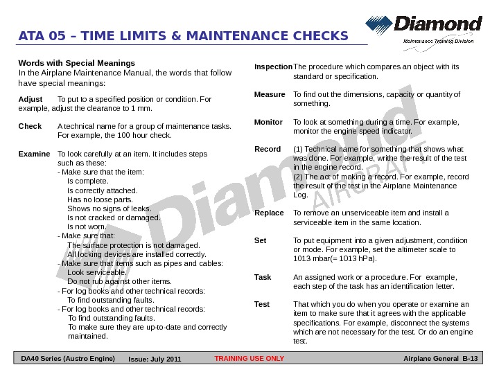
TRAINING USE ONLYATA 05 – TIME LIMITS & MAINTENANCE CHECKS Airplane General B-13 Words with Special Meanings In the Airplane Maintenance Manual, the words that follow have special meanings: Adjust To put to a specified position or condition. For example, adjust the clearance to 1 mm. Check A technical name for a group of maintenance tasks. For example, the 100 hour check. Examine To look carefully at an item. It includes steps such as these: — Make sure that the item: Is complete. Is correctly attached. Has no loose parts. Shows no signs of leaks. Is not cracked or damaged. Is not worn. — Make sure that: The surface protection is not damaged. All locking devices are installed correctly. — Make sure that items such as pipes and cables: Look serviceable. Do not rub against other items. — For log books and other technical records: To find outstanding faults. — For log books and other technical records: To find outstanding faults. To make sure they are up-to-date and correctly maintained. Inspection The procedure which compares an object with its standard or specification. Measure To find out the dimensions, capacity or quantity of something. Monitor To look at something during a time. For example, monitor the engine speed indicator. Record (1) Technical name for something that shows what was done. For example, writhe result of the test in the engine record. (2) The act of making a record. For example, record the result of the test in the Airplane Maintenance Log. Replace To remove an unserviceable item and install a serviceable item in the same location. Set To put equipment into a given adjustment, condition or mode. For example, set the altimeter scale to 1013 mbar(= 1013 h. Pa). Task An assigned work or a procedure. For example, each step of the task has an identification letter. Test That which you do when you operate or examine an item to make sure that it agrees with the applicable specifications. For example, disconnect the systems which are not necessary for the test. Or do an engine test. DA 40 Series (Austro Engine) Issue: July
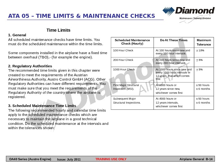
TRAINING USE ONLYATA 05 – TIME LIMITS & MAINTENANCE CHECKS Airplane General B-14 Scheduled Maintenance Check (Hourly) Do At These Times Maximum Tolerance 100 Hour Check At 100 hours since new and every 100 hour intervals. + 10% 200 Hour Check At 200 hours since new and every 200 hour intervals. + 5% 1000 Hour Check At 1000 hours since new and every 1000 hour intervals or 12 years, that which comes first + 5% First Major Structural Inspection (MSI). At 6000 hours or 12 years since new, whichever comes first ± 50 hours ± 6 months Subsequent Major Structural Inspections. At 4000 hours or 12 years intervals, whichever comes first ± 50 hours ± 6 months. Time Limits 1. General All scheduled maintenance checks have time limits. You must do the scheduled maintenance within the time limits. Some components installed in the airplane have a fixed time between overhaul (TBO), — (for example the engine). 2. Regulatory Authorities The recommended time limits given in this chapter were created to meet the requirements of the Austrian Airworthiness Authority, Austro Control Gmb. H (ACG). Other Regulatory Authorities can have different requirements. You must make sure that you meet the requirements of the Regulatory Authority of the country where the airplane is registered. 3. Scheduled Maintenance Time Limits The following recommended hourly and calendar time limits apply to the scheduled maintenance checks which are necessary to maintain the airplane in a good technical condition. Do the scheduled maintenance at the intervals and within the tolerances shown: DA 40 Series (Austro Engine) Issue: July
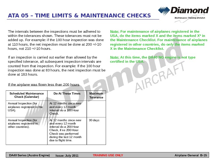
TRAINING USE ONLYATA 05 – TIME LIMITS & MAINTENANCE CHECKS Airplane General B-15 Scheduled Maintenance Check (Calendar) Do At These Times Maximum Tolerance Annual Inspection (for airplanes registered in the USA). At 12 months since new and every 12 month interval do a 100 Hour Check. Annual Inspection (for airplanes registered in other countries). At 12 months since new and every 12 month interval do a 200 Hour Check, if no 200 Hour Check was performed during the last 12 month due to flight time. 30 days. The intervals between the inspections must be adhered to within the tolerances shown. These tolerances must not be added up. For example: if the 100 hour inspection was done at 110 hours, the net inspection must be done at 200 +/-10 hours, not 210 +/-10 hours. If an inspection is carried out earlier than allowed by the specified tolerance, all subsequent inspection intervals are counted from that inspection. For example: If the 100 hour inspection was done at 83 hours, the next inspection must be done at 183 hours. If the airplane was flown less than 200 hours Note: For maintenance of airplanes registered in the USA, do the items marked X and the items marked X* in the Maintenance Checklist. For maintenance of airplanes registered in other countries, do only the items marked X in the Maintenance Checklist. Note: At this time, the DA 40 NG engine is not type certified in the USA. DA 40 Series (Austro Engine) Issue: July
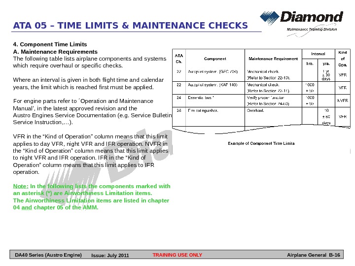
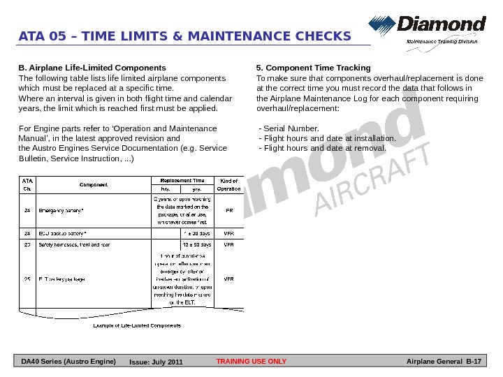
TRAINING USE ONLYATA 05 – TIME LIMITS & MAINTENANCE CHECKS Airplane General B-164. Component Time Limits A. Maintenance Requirements The following table lists airplane components and systems which require overhaul or specific checks. Where an interval is given in both flight time and calendar years, the limit which is reached first must be applied. For engine parts refer to ´Operation and Maintenance Manual’, in the latest approved revision and the Austro Engines Service Documentation (e. g. Service Bulletin, Service Instruction, …). VFR in the “Kind of Operation” column means that this limit applies to day VFR, night VFR and IFR operation. NVFR in the “Kind of Operation” column means that this limit applies to night VFR and IFR operation. IFR in the “Kind of Operation” column means that this limit applies to IFR operation. Note: In the following lists the components marked with an asterisk (*) are Airworthiness Limitation items. The Airworthiness Limitation items are listed in chapter 04 and chapter 05 of the AMM. DA 40 Series (Austro Engine) Issue: July
TRAINING USE ONLYATA 05 – TIME LIMITS & MAINTENANCE CHECKS Airplane General B-175. Component Time Tracking To make sure that components overhaul/replacement is done at the correct time you must record the data that follows in the Airplane Maintenance Log for each component requiring overhaul/replacement: — Serial Number. — Flight hours and date at installation. — Flight hours and date at removal. B. Airplane Life-Limited Components The following table lists life limited airplane components which must be replaced at a specific time. Where an interval is given in both flight time and calendar years, the limit which is reached first must be applied. For Engine parts refer to ‘Operation and Maintenance Manual’, in the latest approved revision and the Austro Engines Service Documentation (e. g. Service Bulletin, Service Instruction, . . . ) DA 40 Series (Austro Engine) Issue: July
Scheduled Maintenance Checks 1. General Do the scheduled maintenance checks in this section at the intervals (flight hours and calendar time) stated in AMM section 05 -10, Paragraph 3. Note: Only persons authorized by national regulatory authorities of the country where the airplane is registered, (or a JAR-145 approved maintenance organization in Europe), may do these checks. The inspection level for each item is a general visual inspection unless differently specified. Note: Only AE authorized maintenance organizations may carry out maintenance and inspection work on the AE engine. Any engine malfunction must be reported to AE. 2. Maintenance Checklist Do the scheduled maintenance checks with reference to the Maintenance Checklist. Do all the applicable tasks on the checklist. All of the applicable items must be signed by authorized maintenance personnel. Record the completion of the check in the airplane log book. Complete a copy of the Maintenance Report. TRAINING USE ONLYATA 05 – TIME LIMITS & MAINTENANCE CHECKS Airplane General B-18 The Maintenance Checklist is divided into the following Sections: A. Engine Compartment: All items forward of the firewall. It includes the cowlings and the propeller. B. Airframe: (1) Front Fuselage All items on the outside of the front fuselage from the firewall to the trailing edge of the wing. It includes the nose landing gear, the main landing gear, the canopy and rear door. (2) Cockpit All items inside the fuselage shell from the aft face of the firewall to the aft face of the rear main bulkhead. It also includes the internal parts of the brake system. (3) Center Fuselage, Internal All items inside the fuselage shell below the rear seats from the aft face of the rear main bulkhead to the baggage compartment. It includes the control systems on the aft main bulkhead and the baggage compartment. DA 40 Series (Austro Engine) Issue: July
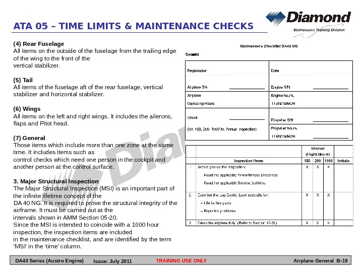
(4) Rear Fuselage All items on the outside of the fuselage from the trailing edge of the wing to the front of the vertical stabilizer. (5) Tail All items of the fuselage aft of the rear fuselage, vertical stabilizer and horizontal stabilizer. (6) Wings All items on the left and right wings. It includes the ailerons, flaps and Pitot head. (7) General Those items which include more than one zone at the same time. It includes items such as control checks which need one person in the cockpit and another person at the control surface. 3. Major Structural Inspection The Major Structural Inspection (MSI) is an important part of the infinite lifetime concept of the DA 40 NG. It is required to prove the structural integrity of the airframe. It must be carried out at the intervals shown in AMM Section 05 -20. Since the MSI is intended to coincide with a 1000 hour inspection, the inspection items are included in the maintenance checklist, and are identified by the term ‘MSI’ in the ‘time’ column. TRAINING USE ONLYATA 05 – TIME LIMITS & MAINTENANCE CHECKS Airplane General B-19 DA 40 Series (Austro Engine) Issue: July
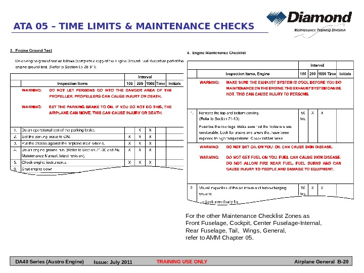
TRAINING USE ONLYATA 05 – TIME LIMITS & MAINTENANCE CHECKS Airplane General B-20 For the other Maintenance Checklist Zones as Front Fuselage, Cockpit, Center Fuselage-Internal, Rear Fuselage, Tail, Wings, General, refer to AMM Chapter 05. DA 40 Series (Austro Engine) Issue: July
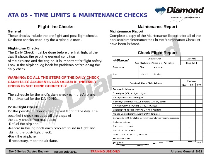
TRAINING USE ONLYATA 05 – TIME LIMITS & MAINTENANCE CHECKS Airplane General B-21 Flight-line Checks General These checks include the pre-flight and post-flight checks. Do these checks each day the airplane is used. Flight-Line Checks The Daily Check must be done before the first flight of the day. It shows the pilot the general condition of the airplane and the engine. It is important for flight safety. Look in the airplane log-book for problems before doing the daily check. WARNING: DO ALL THE STEPS OF THE DAILY CHECK CAREFULLY. ACCIDENTS CAN OCCUR IF THE DAILY CHECK IS NOT DONE CORRECTLY. The schedule for the pilot’s daily check is in the Airplane Flight Manual for the DA 40 NG. Post-Flight Check Do the post-flight check after the last flight of the day. The post-flight check includes all the steps of the daily check. You must also: -Refuel the airplane. -Record in the log book each problem found in flight and during the post-flight check. -Park the airplane. -If necessary, moor the airplane. Maintenance Report Complete a copy of the Maintenance Report after all of the applicable maintenance task in the Maintenance Checklist have been initiated. Check Flight Report DA 40 Series (Austro Engine) Issue: July
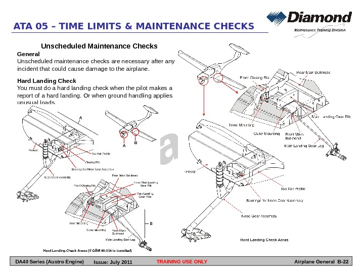
TRAINING USE ONLYATA 05 – TIME LIMITS & MAINTENANCE CHECKS Airplane General B-22 Unscheduled Maintenance Checks General Unscheduled maintenance checks are necessary after any incident that could cause damage to the airplane. Hard Landing Check You must do a hard landing check when the pilot makes a report of a hard landing. Or when ground handling applies unusual loads. DA 40 Series (Austro Engine) Issue: July
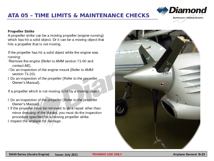
TRAINING USE ONLYATA 05 – TIME LIMITS & MAINTENANCE CHECKS Airplane General B-23 Propeller Strike A propeller strike can be a moving propeller (engine running) which has hit a solid object. Or it can be a moving object that hits a propeller that is not moving. If the propeller has hit a solid object while the engine was running: Remove the engine (Refer to AMM section 71 -00 and contact AE). Do an inspection of the engine mount (Refer to AMM section 71 -20). Do an inspection of the propeller (Refer to the propeller Owner’s Manual). If a propeller which is not moving is hit by a moving object: Do an inspection of the propeller (Refer to the propeller Owner’s Manual). If the propeller must be removed to do a repair other than minor dressing of the blades, you must do the inspection procedure specified for a moving propeller strike. Inspect the airplane for damage. DA 40 Series (Austro Engine) Issue: July
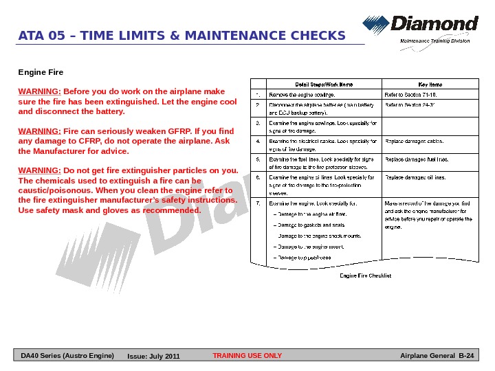
TRAINING USE ONLYATA 05 – TIME LIMITS & MAINTENANCE CHECKS Airplane General B-24 Engine Fire WARNING: Before you do work on the airplane make sure the fire has been extinguished. Let the engine cool and disconnect the battery. WARNING: Fire can seriously weaken GFRP. If you find any damage to CFRP, do not operate the airplane. Ask the Manufacturer for advice. WARNING: Do not get fire extinguisher particles on you. The chemicals used to extinguish a fire can be caustic/poisonous. When you clean the engine refer to the fire extinguisher manufacturer’s safety instructions. Use safety mask and gloves as recommended. DA 40 Series (Austro Engine) Issue: July
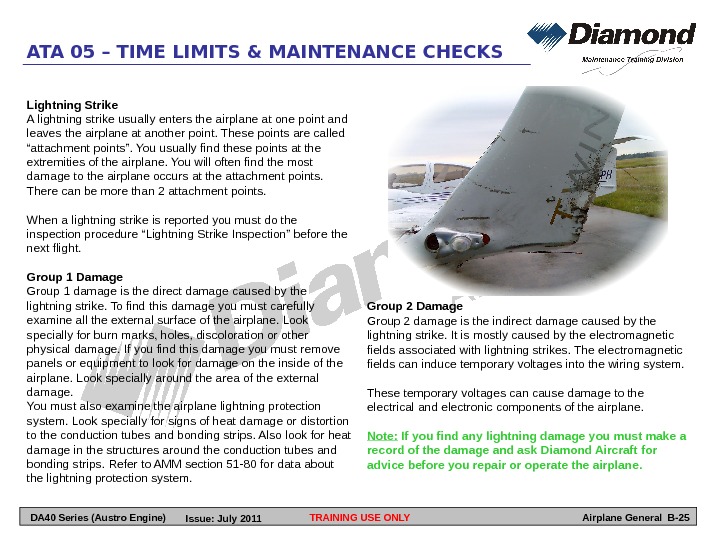
TRAINING USE ONLYATA 05 – TIME LIMITS & MAINTENANCE CHECKS Airplane General B-25 Lightning Strike A lightning strike usually enters the airplane at one point and leaves the airplane at another point. These points are called “attachment points”. You usually find these points at the extremities of the airplane. You will often find the most damage to the airplane occurs at the attachment points. There can be more than 2 attachment points. When a lightning strike is reported you must do the inspection procedure “Lightning Strike Inspection” before the next flight. Group 1 Damage Group 1 damage is the direct damage caused by the lightning strike. To find this damage you must carefully examine all the external surface of the airplane. Look specially for burn marks, holes, discoloration or other physical damage. If you find this damage you must remove panels or equipment to look for damage on the inside of the airplane. Look specially around the area of the external damage. You must also examine the airplane lightning protection system. Look specially for signs of heat damage or distortion to the conduction tubes and bonding strips. Also look for heat damage in the structures around the conduction tubes and bonding strips. Refer to AMM section 51 -80 for data about the lightning protection system. Group 2 Damage Group 2 damage is the indirect damage caused by the lightning strike. It is mostly caused by the electromagnetic fields associated with lightning strikes. The electromagnetic fields can induce temporary voltages into the wiring system. These temporary voltages can cause damage to the electrical and electronic components of the airplane. Note: If you find any lightning damage you must make a record of the damage and ask Diamond Aircraft for advice before you repair or operate the airplane. DA 40 Series (Austro Engine) Issue: July
TRAINING USE ONLYATA 05 – TIME LIMITS & MAINTENANCE CHECKS Airplane General B-26 LEFT BLANK DA 40 Series (Austro Engine) Issue: July
TRAINING USE ONLYATA 06 – DIMENSIONS AND AREAS Airplane General B-27 DA 40 Series (Austro Engine) Issue: July
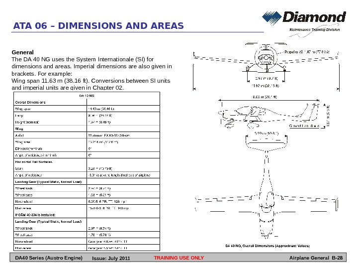
TRAINING USE ONLYATA 06 – DIMENSIONS AND AREAS Airplane General B-28 General The DA 40 NG uses the System Internationale (SI) for dimensions and areas. Imperial dimensions are also given in brackets. For example: Wing span 11. 63 m (38. 16 ft). Conversions between SI units and imperial units are given in Chapter 02. DA 40 Series (Austro Engine) Issue: July
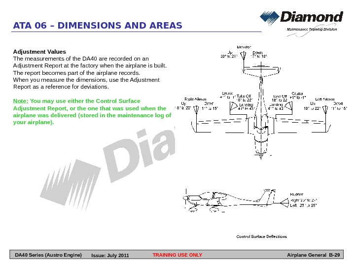
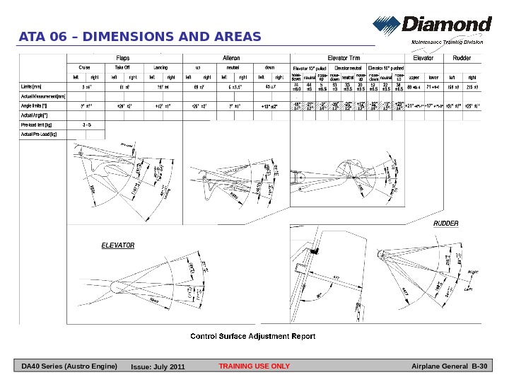
TRAINING USE ONLYATA 06 – DIMENSIONS AND AREAS Airplane General B-29 Adjustment Values The measurements of the DA 40 are recorded on an Adjustment Report at the factory when the airplane is built. The report becomes part of the airplane records. When you measure the dimensions, use the Adjustment Report as a reference for deviations. Note: You may use either the Control Surface Adjustment Report, or the one that was used when the airplane was delivered (stored in the maintenance log of your airplane). DA 40 Series (Austro Engine) Issue: July
TRAINING USE ONLYATA 06 – DIMENSIONS AND AREAS Airplane General B-30 DA 40 Series (Austro Engine) Issue: July
TRAINING USE ONLYATA 06 – DIMENSIONS AND AREAS Airplane General B-31 Weight and Static Moments of Control Surfaces WARNING: If you repaint (or do repairs to) the control surfaces, you must make sure that the weights and static moments of the control surface balancing report. This will prevent control surface flutter. To measure the static moments you must remove the control surface from the airplane. Refer to AMM section 51 -60 for the measuring procedures. If the values are not within the limits in the Control Surface Balancing Report, you must ask the manufacturer for advice before you adjust the balancing weight. DA 40 Series (Austro Engine) Issue: July
TRAINING USE ONLYATA 06 – DIMENSIONS AND AREAS Airplane General B-32 LEFT BLANK DA 40 Series (Austro Engine) Issue: July
TRAINING USE ONLYATA 07 – LIFTING AND SHORING Airplane General B-33 DA 40 Series (Austro Engine) Issue: July
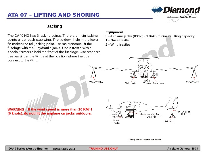
TRAINING USE ONLYATA 07 – LIFTING AND SHORING Airplane General B-34 WARNING : If the wind speed is more than 10 KM/H (6 knots), do not lift the airplane on jacks outdoors. Jacking The DA 40 NG has 3 jacking points. There are main jacking points under each stub-wing. The tie-down hole in the lower fin makes the tail jacking point. For maintenance lift the fuselage with the 3 hydraulic jacks. Use a trestle with a special former to hold the front of the fuselage. Use standard trestles under the wings at the position where the tips connect to the wing. Equipment 3 — Airplane jacks (800 kg / 1764 lb minimum lifting capacity) 1 — Nose trestle 2 — Wing trestles DA 40 Series (Austro Engine) Issue: July
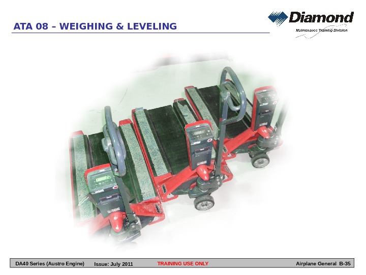
TRAINING USE ONLYATA 08 – WEIGHING & LEVELING Airplane General B-35 DA 40 Series (Austro Engine) Issue: July
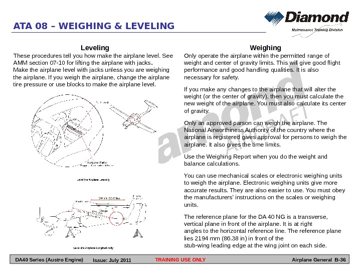
TRAINING USE ONLY Airplane General B-36 ATA 08 – WEIGHING & LEVELING Weighing Only operate the airplane within the permitted range of weight and center of gravity limits. This will give good flight performance and good handling qualities. It is also necessary for safety. If you make any changes to the airplane that will alter the weight (or the center of gravity), then you must calculate the new weight of the airplane. You must also calculate its center of gravity. Only an approved parson can weigh the airplane. The National Airworthiness Authority of the country where the airplane is registered gives approval for persons to weigh the airplane. It also gives the time limits. Use the Weighing Report when you do the weight and balance calculations. You can use mechanical scales or electronic weighing units to weigh the airplane. Electronic weighing units give more accurate results. They are also easier to use. You must obey the manufacturers’ instructions on the scales or weighing units. The reference plane for the DA 40 NG is a transverse, vertical plane in front of the airplane. It is at right angles to the horizontal reference line. The reference plane lies 2194 mm (86. 38 in) in front of the stub-wing leading edge at the wing joint on each side. Leveling These procedures tell you how make the airplane level. See AMM section 07 -10 for lifting the airplane with jacks. Make the airplane level with jacks unless you are weighing the airplane. If you weigh the airplane, change the airplane tire pressure or use blocks to make the airplane level. DA 40 Series (Austro Engine) Issue: July
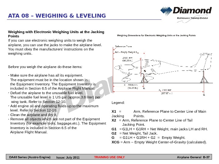
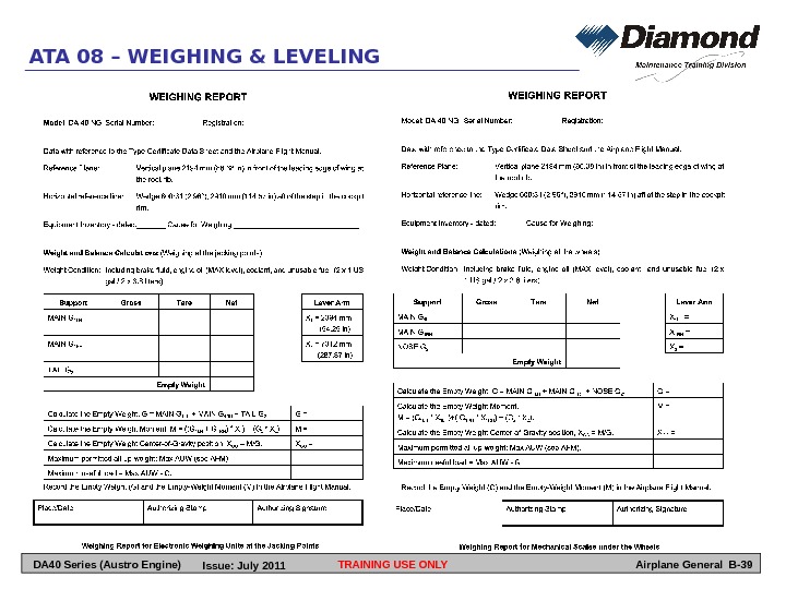
TRAINING USE ONLY Airplane General B-37 ATA 08 – WEIGHING & LEVELING Weighing with Electronic Weighing Units at the Jacking Points If you can use electronic weighing units to weigh the airplane, you can use the jacks to make the airplane level. You must obey the manufacturers’ instructions on the weighing units. Before you weigh the airplane do these items: — Make sure the airplane has all its equipment. The equipment must be in the location shown in the Equipment Inventory. The Equipment Inventory is included in Section 6. 5 of the Airplane Flight Manual. — Defuel the airplane to the unusable fuel level. The unusable fuel level is 1 US gal (approx. 3. 8 liter) per wing tank. Refer to Section 12 -10. — Add engine oil and operating fluids up to the maximum level. Refer to Section 12 -10. — Clean the airplane and dry it. — Remove all objects which are not part of the Equipment Inventory (for example tools, baggage, etc. ). The Equipment Inventory is included in Section 6. 5 of the Airplane Flight Manual. Legend: X 1 = Arm, Reference Plane to Center Line of Main Jacking Points. X 2 = Arm, Reference Plane to Center Line of Tail Jacking Point. G 1 = G 1 LH + G 1 RH = Net Weight, main jacks LH and RH. G 2 = Net Weight, Tail Jack. G = G 1 LH + G 1 RH + G 2 = Empty Weight. XCG = Arm – Empty Weight Center-of-Gravity (calculated). DA 40 Series (Austro Engine) Issue: July
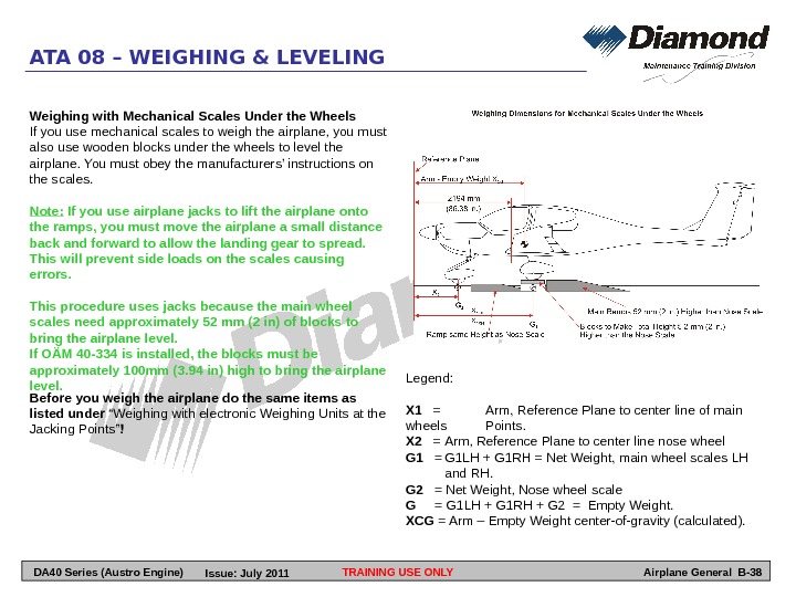
TRAINING USE ONLY Airplane General B-38 ATA 08 – WEIGHING & LEVELING Weighing with Mechanical Scales Under the Wheels If you use mechanical scales to weigh the airplane, you must also use wooden blocks under the wheels to level the airplane. You must obey the manufacturers’ instructions on the scales. Note: If you use airplane jacks to lift the airplane onto the ramps, you must move the airplane a small distance back and forward to allow the landing gear to spread. This will prevent side loads on the scales causing errors. This procedure uses jacks because the main wheel scales need approximately 52 mm (2 in) of blocks to bring the airplane level. If OÄM 40 -334 is installed, the blocks must be approximately 100 mm (3. 94 in) high to bring the airplane level. Legend: X 1 = Arm, Reference Plane to center line of main wheels Points. X 2 = Arm, Reference Plane to center line nose wheel G 1 = G 1 LH + G 1 RH = Net Weight, main wheel scales LH and RH. G 2 = Net Weight, Nose wheel scale G = G 1 LH + G 1 RH + G 2 = Empty Weight. XCG = Arm – Empty Weight center-of-gravity (calculated). Before you weigh the airplane do the same items as listed under “Weighing with electronic Weighing Units at the Jacking Points” ! DA 40 Series (Austro Engine) Issue: July
TRAINING USE ONLY Airplane General B-39 ATA 08 – WEIGHING & LEVELING DA 40 Series (Austro Engine) Issue: July
TRAINING USE ONLYATA 09 – TOWING AND TAXIING Airplane General B-40 DA 40 Series (Austro Engine) Issue: July
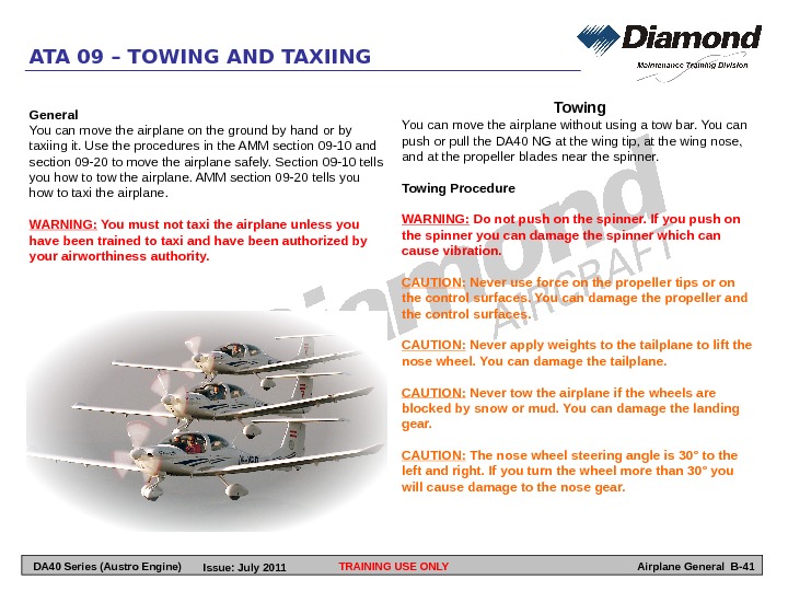
TRAINING USE ONLYATA 09 – TOWING AND TAXIING Airplane General B-41 General You can move the airplane on the ground by hand or by taxiing it. Use the procedures in the AMM section 09 -10 and section 09 -20 to move the airplane safely. Section 09 -10 tells you how to tow the airplane. AMM section 09 -20 tells you how to taxi the airplane. WARNING: You must not taxi the airplane unless you have been trained to taxi and have been authorized by your airworthiness authority. Towing You can move the airplane without using a tow bar. You can push or pull the DA 40 NG at the wing tip, at the wing nose, and at the propeller blades near the spinner. Towing Procedure WARNING: Do not push on the spinner. If you push on the spinner you can damage the spinner which can cause vibration. CAUTION: Never use force on the propeller tips or on the control surfaces. You can damage the propeller and the control surfaces. CAUTION: Never apply weights to the tailplane to lift the nose wheel. You can damage the tailplane. CAUTION: Never tow the airplane if the wheels are blocked by snow or mud. You can damage the landing gear. CAUTION: The nose wheel steering angle is 30° to the left and right. If you turn the wheel more than 30° you will cause damage to the nose gear. DA 40 Series (Austro Engine) Issue: July
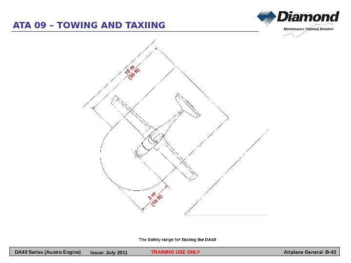
TRAINING USE ONLYATA 09 – TOWING AND TAXIING Airplane General B-42 A. Forward Movement Pull the airplane forward on the propeller blades near the spinner. The nose wheel will follow the movement of the airplane. You can change direction by pulling on the appropriate propeller blade near the spinner. B. Rearward Movement Push down the fuselage in front of the vertical stabilizer until the nose wheel is clear of the ground while pushing the airplane in rearward direction. C. Turn the Airplane on the Ground If you have a limited area to maneuver the airplane, you can use 2 people to turn the airplane around the main wheels. One person must push down in front of the vertical stabilizer until the nose wheel is clear of the ground. The other person must push on the wing tip. Taxiing When you taxi the DA 40 NG you use the toe operated brakes to steer the airplane. To make the airplane turn operate the left or the right toe brake. WARNING: You must not taxi the airplane unless you have been trained to taxi and have been authorized by your airworthiness authority. CAUTION: This section gives general data on taxiing only. You must use the DA 40 NG Airplane Flight Manual when you taxi the airplane. WARNING: Make sure that there are no persons or objects near the airplane. The airplane can injure persons. Objects can damage the airplane. WARNING: Make sure the brakes operate correctly when you taxi the airplane. If the brakes should fail, you must be able to stop the airplane before you hit persons or equipment. CAUTION: Take care if you taxi on uneven ground. The propeller must not touch the ground. Loose stones and gravel can damage the propeller. CAUION: Obey the safety range for taxiing shown in figure below: DA 40 Series (Austro Engine) Issue: July
TRAINING USE ONLYATA 09 – TOWING AND TAXIING Airplane General B-43 DA 40 Series (Austro Engine) Issue: July
TRAINING USE ONLYATA 09 – TOWING AND TAXIING Airplane General B-44 LEFT BLANK DA 40 Series (Austro Engine) Issue: July
TRAINING USE ONLYATA 10 – PARKING & MOORING Airplane General B-45 DA 40 Series (Austro Engine) Issue: July
Parking and Storage Use these procedures to protect the airplane when it is parked. Use the short-term parking procedure when the airplane will be parked for less than 5 days. Use the long term parking procedure when the airplane will be parked for 5 to 30 days. Use the storage procedure if the airplane will be parked for more than 30 days. All pilots and all maintenance staff for the DA 40 NG must know the procedures in this section. CAUTION: Make sure that the airplane is correctly moored and protected if strong winds are forecast. Strong winds can cause damage to an unprotected airplane. TRAINING USE ONLY Airplane General B-46 ATA 10 – PARKING & MOORING Short-Term Parking CAUTION: Make sure that the nose wheel is aligned straight ahead when the airplane stops. This will prevent side loads which can damage the nose landing gear. CAUTION: Do not apply the parking brake when the brakes are over-heated. The brakes can seize on. Long-Term Parking CAUTION: Make sure to perform the long term parking procedure when the airplane is parked for a long time. If the procedure is not followed correctly, damage to the airplane can occur. Storage If the airplane is parked (or not operated) for more than 30 days, you must do the storage procedure according to the AMM. If the airplane has been parked (or stored) for more than 5 days, perform Return to Service procedure!General Always park or moor the DA 40 NG when it is not in use. Use the procedures in the AMM section 10 -10 for parking the airplane and the procedure in section 10 -20 to moor the airplane. If the airplane is parked over-night, we recommend that you moor the airplane. If strong winds are forecast, you must always moor the airplane. DA 40 Series (Austro Engine) Issue: July
TRAINING USE ONLY Airplane General B-47 ATA 10 – PARKING & MOORING Mooring CAUTION: If the airplane must be stored outside for a long time, then you must moor it. Strong winds or gusts can cause damage to an airplane which is not moored. There are 3 mooring points: One below each wing and one on the skid plat at the tail. CAUTION: Moor the airplane at the mooring points only. CAUTION: When using hemp ropes, do not make them tight. If the ropes get wet they will tighten and damage the airplane. This is most important when you use secure ground anchor-point. DA 40 Series (Austro Engine) Issue: July
TRAINING USE ONLY Airplane General B-48 ATA 10 – PARKING & MOORING LEFT BLANK DA 40 Series (Austro Engine) Issue: July
TRAINING USE ONLYATA 11 – PLACARDS & MARKINGS Airplane General B-49 DA 40 Series (Austro Engine) Issue: July
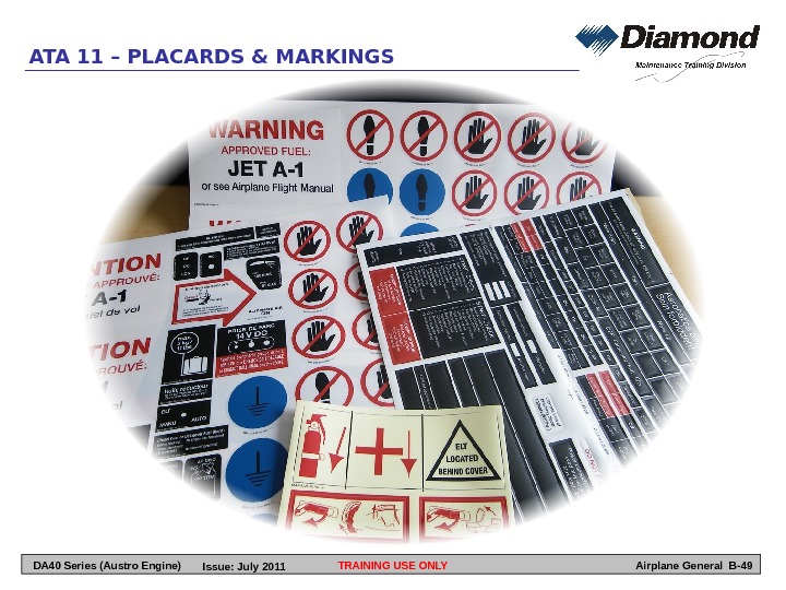
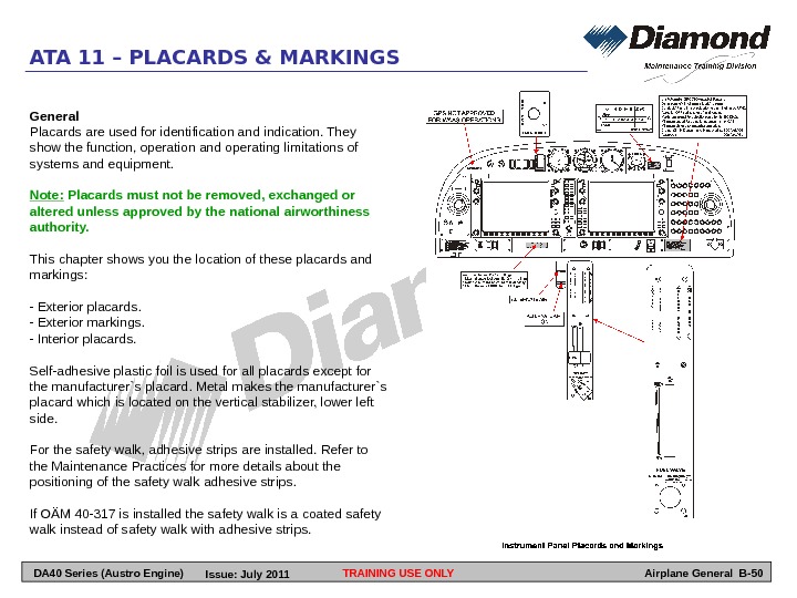
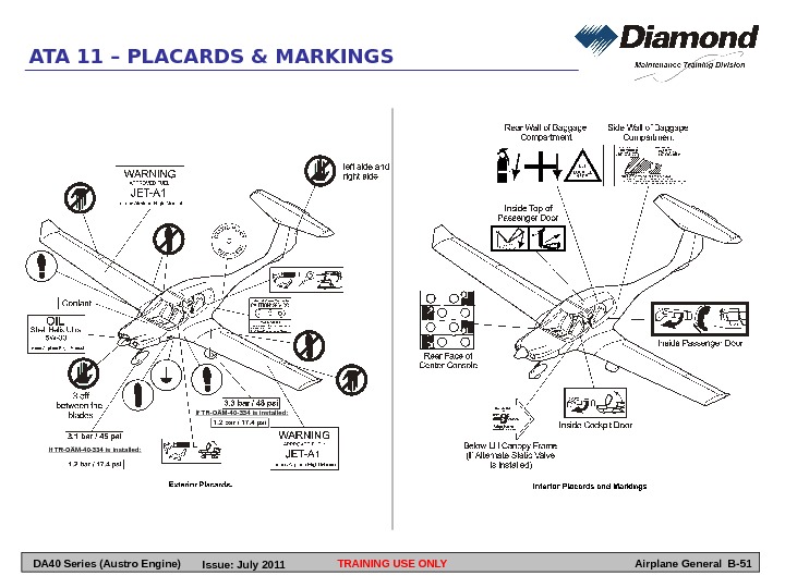
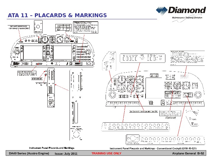
TRAINING USE ONLY Airplane General B-50 ATA 11 – PLACARDS & MARKINGS General Placards are used for identification and indication. They show the function, operation and operating limitations of systems and equipment. Note: Placards must not be removed, exchanged or altered unless approved by the national airworthiness authority. This chapter shows you the location of these placards and markings: — Exterior placards. — Exterior markings. — Interior placards. Self-adhesive plastic foil is used for all placards except for the manufacturer`s placard. Metal makes the manufacturer`s placard which is located on the vertical stabilizer, lower left side. For the safety walk, adhesive strips are installed. Refer to the Maintenance Practices for more details about the positioning of the safety walk adhesive strips. If OÄM 40 -317 is installed the safety walk is a coated safety walk instead of safety walk with adhesive strips. DA 40 Series (Austro Engine) Issue: July
TRAINING USE ONLY Airplane General B-51 ATA 11 – PLACARDS & MARKINGS DA 40 Series (Austro Engine) If TR-OÄM-40 -334 is installed: Issue: July
TRAINING USE ONLY Airplane General B-52 ATA 11 – PLACARDS & MARKINGS DA 40 Series (Austro Engine) Issue: July
TRAINING USE ONLYATA 12 – SERVICING Airplane General B-53 DA 40 Series (Austro Engine) Issue: July
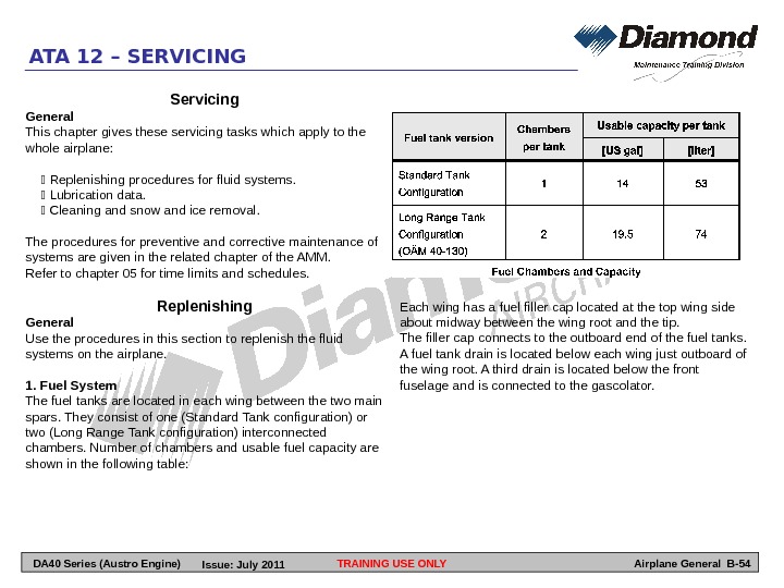
TRAINING USE ONLYATA 12 – SERVICING Airplane General B-54 Servicing General This chapter gives these servicing tasks which apply to the whole airplane: Replenishing procedures for fluid systems. Lubrication data. Cleaning and snow and ice removal. The procedures for preventive and corrective maintenance of systems are given in the related chapter of the AMM. Refer to chapter 05 for time limits and schedules. Replenishing General Use the procedures in this section to replenish the fluid systems on the airplane. 1. Fuel System The fuel tanks are located in each wing between the two main spars. They consist of one (Standard Tank configuration) or two (Long Range Tank configuration) interconnected chambers. Number of chambers and usable fuel capacity are shown in the following table: Each wing has a fuel filler cap located at the top wing side about midway between the wing root and the tip. The filler cap connects to the outboard end of the fuel tanks. A fuel tank drain is located below each wing just outboard of the wing root. A third drain is located below the front fuselage and is connected to the gascolator. DA 40 Series (Austro Engine) Issue: July
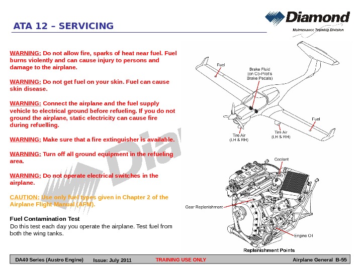
TRAINING USE ONLYATA 12 – SERVICING Airplane General B-55 WARNING: Do not allow fire, sparks of heat near fuel. Fuel burns violently and can cause injury to persons and damage to the airplane. WARNING: Do not get fuel on your skin. Fuel can cause skin disease. WARNING: Connect the airplane and the fuel supply vehicle to electrical ground before refueling. If you do not ground the airplane, static electricity can cause fire during refuelling. WARNING: Make sure that a fire extinguisher is available. WARNING: Turn off all ground equipment in the refueling area. WARNING: Do not operate electrical switches in the airplane. CAUTION: Use only fuel types given in Chapter 2 of the Airplane Flight Manual (AFM). Fuel Contamination Test Do this test each day you operate the airplane. Test fuel from both the wing tanks. DA 40 Series (Austro Engine) Issue: July
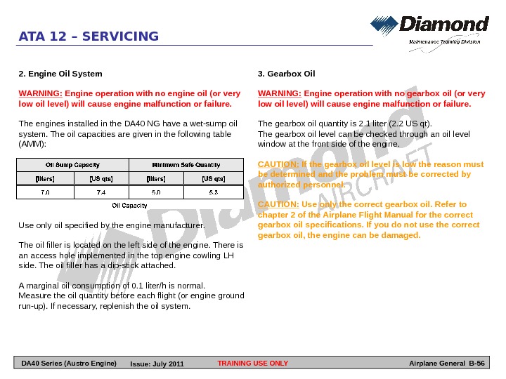
TRAINING USE ONLYATA 12 – SERVICING Airplane General B-562. Engine Oil System WARNING: Engine operation with no engine oil (or very low oil level) will cause engine malfunction or failure. The engines installed in the DA 40 NG have a wet-sump oil system. The oil capacities are given in the following table (AMM): Use only oil specified by the engine manufacturer. The oil filler is located on the left side of the engine. There is an access hole implemented in the top engine cowling LH side. The oil filler has a dip-stick attached. A marginal oil consumption of 0. 1 liter/h is normal. Measure the oil quantity before each flight (or engine ground run-up). If necessary, replenish the oil system. 3. Gearbox Oil WARNING: Engine operation with no gearbox oil (or very low oil level) will cause engine malfunction or failure. The gearbox oil quantity is 2. 1 liter (2. 2 US qt). The gearbox oil level can be checked through an oil level window at the front side of the engine. CAUTION: If the gearbox oil level is low the reason must be determined and the problem must be corrected by authorized personnel. CAUTION: Use only the correct gearbox oil. Refer to chapter 2 of the Airplane Flight Manual for the correct gearbox oil specifications. If you do not use the correct gearbox oil, the engine can be damaged. DA 40 Series (Austro Engine) Issue: July
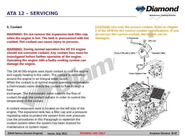
TRAINING USE ONLYATA 12 – SERVICING Airplane General B-574. Coolant WARNING: Do not remove the expansion tank filler cap when the engine is hot. The tank is pressurized with hot coolant. Hot coolant can cause injury to persons. WARNING: During normal operation the AE E 4 engine should not consume coolant. Any coolant loss must be investigated before further operation of the engine. Operating the engine with a faulty cooling system can damage the engine. The DA 40 NG engine uses liquid coolant to cool the engine and supply heating to the cabin. The coolant is circulated around the engine in an integral water jacket. When the coolant is at normal engine operating temperature a thermostatic valve directs the coolant to flow through a heat exchanger. The thermostatic valve controls the flow of coolant through the coolant radiator in order to control the temperature of the coolant. A coolant expansion tank is located on the left side of the engine. The expansion tank has a filler cap and a pressure regulating valve to protect the system from over pressure. Use the procedures in this Paragraph to replenish the coolant system when the system has been drained for maintenance or system repair. CAUTION: Use only the correct coolant. Refer to chapter 2 of the AFM for the correct coolant specifications. If you do not use the correct coolant, the engine can be damaged. DA 40 Series (Austro Engine) Issue: July
TRAINING USE ONLYATA 12 – SERVICING Airplane General B-58 DA 40 Series (Austro Engine) Issue: July
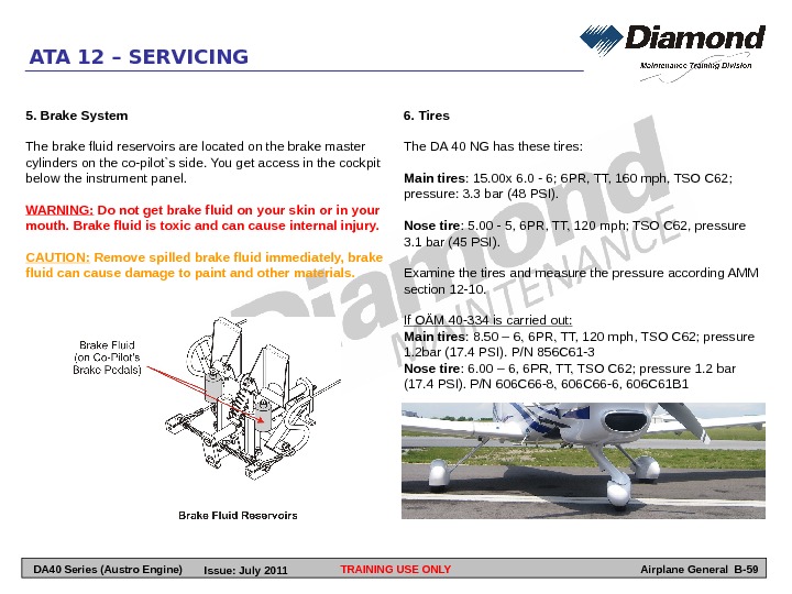
TRAINING USE ONLYATA 12 – SERVICING Airplane General B-596. Tires The DA 40 NG has these tires: Main tires : 15. 00 x 6. 0 — 6; 6 PR, TT, 160 mph, TSO C 62; pressure: 3. 3 bar (48 PSI). Nose tire : 5. 00 — 5, 6 PR, TT, 120 mph; TSO C 62, pressure 3. 1 bar (45 PSI). Examine the tires and measure the pressure according AMM section 12 -10. If OÄM 40 -334 is carried out: Main tires : 8. 50 – 6, 6 PR, TT, 120 mph, TSO C 62; pressure 1. 2 bar (17. 4 PSI). P/N 856 C 61 -3 Nose tire : 6. 00 – 6, 6 PR, TT, TSO C 62; pressure 1. 2 bar (17. 4 PSI). P/N 606 C 66 -8, 606 C 66 -6, 606 C 61 B 15. Brake System The brake fluid reservoirs are located on the brake master cylinders on the co-pilot`s side. You get access in the cockpit below the instrument panel. WARNING: Do not get brake fluid on your skin or in your mouth. Brake fluid is toxic and can cause internal injury. CAUTION: Remove spilled brake fluid immediately, brake fluid can cause damage to paint and other materials. DA 40 Series (Austro Engine) Issue: July
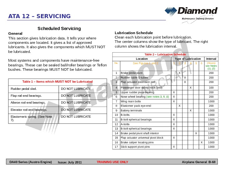
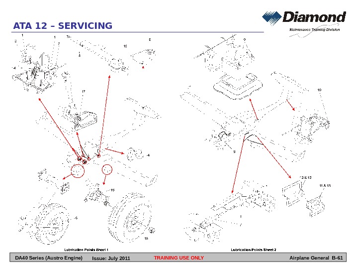
TRAINING USE ONLYATA 12 – SERVICING Airplane General B-60 Table 1 – Items which MUST NOT be Lubricated Rudder pedal sled. DO NOT LUBRICATE Flap rod-end bearings. DO NOT LUBRICATE Aileron rod-end bearings. DO NOT LUBRICATE Elevator rod-end bearings. DO NOT LUBRICATE Elastomeric spring. (See Note 7). DO NOT LUBRICATE Table 2 – Lubrication Schedule Location Type of Lubrication Interval No. See Figures 1 and 2 1 2 3 4 5 6 (Hours) see Notes (1), (2) 1 Brake pedal pivot X 200 2 Rudder cable S-tubes X 200 3 Flap actuator extension rod X 200 4 Passenger door safety hook (red) X 100 5 Upper rudder pivot bearing X 200 6 Nose wheel bearing (see notes 3, 5 , 6) X 200 7 Wing main bolts X 1000 8 Elastomer pack eye-end X 200 9 Battery terminals X 1000 10 B-bolts. X 1000 11 B-bolt spherical bearings X 1000 12 A-bolts X 1000 13 B-bolt spherical bearings X 1000 14 Brake pedal pivot shaft interior X 1000 15 Flap actuator universal pivot block X 1000 16 Brake caliper locating pins X 1000 17 Stick support pivot pins X 1000 Scheduled Servicing General This section gives lubrication data. It tells your where components are located. It gives a list of approved lubricants. It also gives the components which MUST NOT be lubricated. Most systems and components have maintenance-free bearings. These can be sealed ball/roller bearings or Teflon bushes. These bearings MUST NOT be lubricated. Lubrication Schedule Clean each lubrication point before lubrication. The center columns show the type of lubricant. The right column shows the lubrication interval. DA 40 Series (Austro Engine) Issue: July
TRAINING USE ONLYATA 12 – SERVICING Airplane General B-61 DA 40 Series (Austro Engine) Issue: July
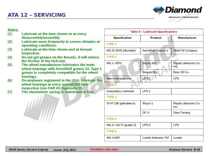
Notes: (1) Lubricate at the time shown or at every disassembly/assembly. (2) Lubricate more frequently in severe climates or operating conditions. (3) Lubricate at the time shown and at Annual Inspection. (4) Do not get grease on the threads. It will reduce the friction of the lock-nut. (5) The wheel manufacturer lubricates the main wheel bearings with Aero. Shell grease 22. Type 1 grease is completely compatible for the wheel bearings. (6) On airplanes registered in the USA, lubricate the wheel bearings at every annual/100 hour inspection (see FAR 43, Appendix D). (7) The elastomeric spring is maintenance free. TRAINING USE ONLYATA 12 – SERVICING Airplane General B-62 Table 3 – Lubricant Specifications Specification Product Manufacturer TYPE 1 MIL-G-3545 (obsolete) Aero. Shell Grease 5 Shell Oil Company TYPE 2 MIL-L-7870 Royco 363 Royal Lubricants Co. Inc. Brayco 363 Bray Oil Co. Warm climates only LPS 2 LPS TYPE 3 Greaseless Lubricant LPS 1 TYPE 4 VV-P-236 (petrolatum) Royco 1 Royal Lubricants Co. Inc. DC 4 Dow Corning TYPE 5 MIL-C-16173 (grade 2) LPS 3 LPS TYPE 6 MIL-A-907 Loctite Antiseize 767 Loctite DA 40 Series (Austro Engine) Issue: July
TRAINING USE ONLYATA 12 – SERVICING Airplane General B-63 Unscheduled Servicing General This section tells you how to clean the airplane. It also tells you how to remove snow and ice from the airplane. 1. Exterior Cleaning The outer surfaces of the DA 40 NG must be kept clean to keep the good performance characteristics of the airplane. The leading edges of the wings are specially important. Protect all control surface bearings and other lubricated components before cleaning the airplane. Use large quantities of water to clean the airplane. If necessary, add a mild cleaning agent to the water. Remove excess dirt or dead insects immediately after flight. Dried-on dirt is difficult to remove. CAUTION: Do not use cleaning or polishing agents which contain silicone. If the airplane needs repair, silicone can prevent repair materials from bonding correctly. Approximately once a year, apply a silicone-free automotive polish to the outer surface. 2. Canopy Cleaning CAUTION: Do not rub the canopy while it is dry. Do not use dirty cloths or sponges. The acrylic canopy scratches very easily with even the smallest particles of dust. Clean the canopy with large quantities of water. Use clean sponges and a good chamois leather which is not used for any other purpose. Polish dull or scratched areas using a special acrylic cleaner. Remove scratches with special polishing emery cloth (e. g. Micro-mesh). 3. Interior Cleaning Clean the interior with a flame-proof vacuum cleaner. All plastic surfaces should be wiped clean using a damp cloth without any cleaning agents. CAUTION: If Installed, the PFD and MFD displays of the Garmin G 1000 use a lens coated with a special anti-reflective coating that is very sensitive to skin oils, waxes, and abrasive cleaners. Cleaners containing ammonia will harm the anti-reflective coating. It is very important to clean the lens using a clean, lint-free cloth and eyeglass lens cleaner that is specified as safe for anti-reflective coatings. DA 40 Series (Austro Engine) Issue: July
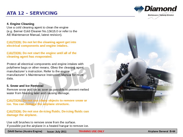
TRAINING USE ONLYATA 12 – SERVICING Airplane General B-644. Engine Cleaning Use a cold cleaning agent to clean the engine (e. g. Berner Cold Cleaner No. 13618. 0 or refer to the AE Maintenance Manual, latest revision). CAUTION: Do not let the cleaning agent get into electrical components and engine intakes. CAUTION: Do not start the engine until all of the cleaning agent has evaporated. Protect all electrical components and engine intakes with polythene bags or other means. Obey the cleaning agent manufacturer´s instruction. Refer to the engine manufacturer`s Maintenance Instruction Manual for more data. 5. Snow and Ice Removal Remove snow and ice as soon as possible to prevent melted water from freezing later and causing damage. CAUTION: Do not use sharp objects to remove snow or ice. You can damage the airplane structure. CAUTION: Do not use de-icing fluids. De-icing fluids can damage the airplane. Use soft brushes to remove snow from the surface. If possible put the airplane in a heated hangar to remove ice. DA 40 Series (Austro Engine) Issue: July