
GROUP A — INTRODUCTION TRAINING USE ONLY Introduction


- Размер: 1.5 Mегабайта
- Количество слайдов: 12
Описание презентации GROUP A — INTRODUCTION TRAINING USE ONLY Introduction по слайдам
GROUP A — INTRODUCTION TRAINING USE ONLY Introduction A-01 ATA-chapter 01 / INTRODUCTION ATA-chapter 02 / MANUAL SYSTEM DA 40 Series (Austro Engine) Issue: July
TRAINING USE ONLYATA 01 — INTRODUCTION Introduction A-02 DA 40 Series (Austro Engine) Issue: July
TRAINING USE ONLY Revision Service The manufacturer provides a revision service for the Airplane Maintenance Manual. The revision shows design changes to the airplane or changes in procedures. Each page of the manual shows the date of first issue. If the page has changed, it shows the date of the revision. Warnings, Cautions and Notes Obey all the usual safety precautions and maintenance instructions when doing maintenance. This Airplane Maintenance Manual also contains warnings, cautions and notes before applicable instructions: WARNING: A WARNING TELLS THE PERSON DOING THE MAINTENANCE THAT INJURY OR DEATH IS POSSIBLE IF THEY DO NOT FOLLOW THE INSTRUCTIONS. CAUTION: A CAUTION TELLS THE PERSON DOING THE MAINTENANCE THAT DAMAGE TO EQUIPMENT IS POSSIBLE IF THEY DO NOT FOLLOW THE INSTRUCTIONS. Note: A Note tells the person doing the maintenance how to make the task easier. ATA 01 — INTRODUCTION Introduction A-03 General The Airplane Maintenance Manual contains the data necessary to do the maintenance of the DA 40 NG. It contains a full description of the systems, trouble shooting procedures, removal and installation procedures and maintenance instructions. It does not contain maintenance data for components removed from the airplane (maintenance shop data). The Airplane Maintenance Manual contains wiring diagrams for the electrical system. Use these manuals with the Airplane Maintenance Manual, and the related Service Bulletins: — The DA 40 NG Illustrated Parts Catalogue. — The DA 40 NG Airplane Flight Manual. — The ELT Manufacturer’s Operator’s Manual. — The mt-Propeller Owner’s Manual. — The Austro Engine Operation Manual, Doc. No. E 4. 01. — The Austro Engine Maintenance Manual, Doc. No. E 4. 08. 04. — The Austro Engine Installation Manual, Doc. No. E 4. 02. 01. — The mt-Propeller Operation and Installation Manual for the hydraulic constant speed governor. — The Garmin G 1000 Line Maintenance Manual. — The Garmin GFC 700 Troubleshooting Reference. — The Garmin DA 40 NG Pilot’s Guide (GFC 700). DA 40 Series (Austro Engine) Issue: July
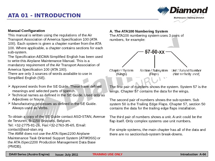
TRAINING USE ONLY A. The ATA 100 Numbering System The ATA 100 numbering system uses 3 pairs of numbers, for example: The first pair of numbers shows the system. System 57 is the wings. Chapter 57 contains the data for the wings. The second pair of numbers shows the sub-system. Sub system 50 is the Trailing Edge Flaps. Chapter 57, section 50 contains the data for the trailing edge flaps installation. The third pair of numbers shows a unit. A unit could be the flap itself. Only complex systems use unit numbers. For simple systems, the main chapter has all of the data and there are no section/sub-system break-downs. ATA 01 — INTRODUCTION Introduction A-04 Manual Configuration This manual is written using the regulations of the Air Transport Association of America Specification 100 (ATA 100). Each system is given a chapter number from the ATA 100. Where applicable, a chapter contains sections for each sub-system. The Specification AECMA Simplified English has been used to write this Airplane Maintenance Manual. This is a mandatory requirement of the Air Transport Association of America Specification 100 (ATA 100). There are only 3 sources of words available to use in Simplified English (SE). Approved words from the SE Guide. These have defined meanings and selected parts of speech. Technical names as defined in the SE Guide. Used only as Adjectives or Nouns. Manufacturing processes as defined in the SE Guide. Always used as Verbs. To obtain a copy of the SE Guide contact ASD-STAN, Avenue de Tervuren, B-1150 Brussels, Belgium. Tel: +32 -2775 -81 -26, Fax: +32 -2763 -35 -65, Email: contact@asd-stan. org The AMM does not use the ATA i. Spec 2200 Airplane Maintenance Task Oriented Support System (ATMOSS) or the ATA i. Spec 2200 Production Management Data Base (PMDB). DA 40 Series (Austro Engine) Issue: July
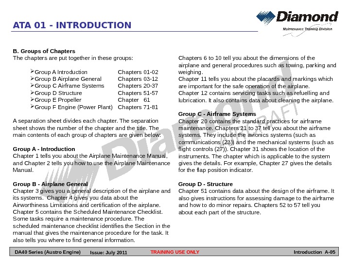
B. Groups of Chapters The chapters are put together in these groups: Group A Introduction Chapters 01 -02 Group B Airplane General Chapters 03 -12 Group C Airframe Systems Chapters 20 -37 Group D Structure Chapters 51 -57 Group E Propeller Chapter 61 Group F Engine (Power Plant) Chapters 71 -81 A separation sheet divides each chapter. The separation sheet shows the number of the chapter and the title. The main contents of each group of chapters are given below: Group A — Introduction Chapter 1 tells you about the Airplane Maintenance Manual, and Chapter 2 tells you how to use the Airplane Maintenance Manual. Group B — Airplane General Chapter 3 gives you a general description of the airplane and its systems. Chapter 4 gives you data about the Airworthiness Limitations and certification of the airplane. Chapter 5 contains the Scheduled Maintenance Checklist. Some tasks require a maintenance procedure. The scheduled maintenance checklist identifies the Section in the manual that gives the maintenance procedure for the task. It also tells you where to find general information. TRAINING USE ONLY Chapters 6 to 10 tell you about the dimensions of the airplane and general procedures such as towing, parking and weighing. Chapter 11 tells you about the placards and markings which are important for the safe operation of the airplane. Chapter 12 contains servicing tasks such as refuelling and lubrication. It also contains data about cleaning the airplane. Group C — Airframe Systems Chapter 20 contains the standard practices for airframe maintenance. Chapters 21 to 37 tell you about the airframe systems. They include the avionics systems (such as communications (23)) and the mechanical systems (such as flight controls (27)). Chapter 31 shows the location of the instruments. The chapter which is applicable to the system gives the details. For example, Chapter 27 gives the details for the flap position indicator. Group D — Structure Chapter 51 contains data about the design of the airframe. It also gives instructions for assessing damage to the airframe and how to do minor repairs. Chapters 52 to 57 tell you about each part of the structure. ATA 01 — INTRODUCTION Introduction A-05 DA 40 Series (Austro Engine) Issue: July
Group E — Propeller Chapter 61 contains the maintenance procedures for the propeller. Refer to the propeller manufacturer’s manual for other data. Group F – Engine This group of chapters describes the engine and its systems. It contains the maintenance procedures for maintenance of the engine on the airplane. Refer to the engine manufacturer’s manual for other data. Chapter Configuration The first page of each chapter shows the number of the chapter and the title. The second page shows the contents. Where applicable, each chapter and section contains the topics that follow: Description and Operation. Trouble-Shooting. Maintenance Practices. Where applicable the Maintenance Practices give data on these procedures: Servicing Removal and Installation Adjustment/Tests Checking/Testing Cleaning/Painting Repairs TRAINING USE ONLY Page Numbering System The Airplane Maintenance Manual uses the ATA 100 page block-numbering system. The page number is at the bottom of the page at the outer edge. It is adjacent to the chapter/section number. Each topic in a section has numbers from these page blocks: • Description and Operation Pages 1 to 99. • Trouble Shooting Pages 101 to 199. • Maintenance Procedures Pages 201 to 299. Figures are given numbers in sequence. The first figure in a chapter or section is figure 1. Record of Revisions The Airplane Maintenance Manual has a Record of Revisions. Use the Record of Revisions to show when changes were included in the Airplane Maintenance Manual. List of Effective Pages This Airplane Maintenance Manual has a List of Effective Pages. The List of Effective Pages shows you the number and effective date of each page contained in the Airplane Maintenance Manual. ATA 01 — INTRODUCTION Introduction A-06 DA 40 Series (Austro Engine) Issue: July
ATA 02 – MANUAL SYSTEM TRAINING USE ONLY Introduction A-07 DA 40 Series (Austro Engine) Issue: July
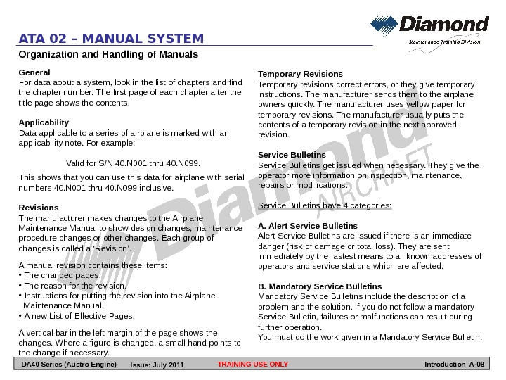
Organization and Handling of Manuals General For data about a system, look in the list of chapters and find the chapter number. The first page of each chapter after the title page shows the contents. Applicability Data applicable to a series of airplane is marked with an applicability note. For example: Valid for S/N 40. N 001 thru 40. N 099. This shows that you can use this data for airplane with serial numbers 40. N 001 thru 40. N 099 inclusive. Revisions The manufacturer makes changes to the Airplane Maintenance Manual to show design changes, maintenance procedure changes or other changes. Each group of changes is called a ‘Revision’. A manual revision contains these items: • The changed pages. • The reason for the revision. • Instructions for putting the revision into the Airplane Maintenance Manual. • A new List of Effective Pages. A vertical bar in the left margin of the page shows the changes. Where a figure is changed, a small hand points to the change if necessary. ATA 02 – MANUAL SYSTEM TRAINING USE ONLY Temporary Revisions Temporary revisions correct errors, or they give temporary instructions. The manufacturer sends them to the airplane owners quickly. The manufacturer uses yellow paper for temporary revisions. The manufacturer usually puts the contents of a temporary revision in the next approved revision. Service Bulletins get issued when necessary. They give the operator more information on inspection, maintenance, repairs or modifications. Service Bulletins have 4 categories: A. Alert Service Bulletins are issued if there is an immediate danger (risk of damage or total loss). They are sent immediately by the fastest means to all known addresses of operators and service stations which are affected. B. Mandatory Service Bulletins include the description of a problem and the solution. If you do not follow a mandatory Service Bulletin, failures or malfunctions can result during further operation. You must do the work given in a Mandatory Service Bulletin. Introduction A-08 DA 40 Series (Austro Engine) Issue: July
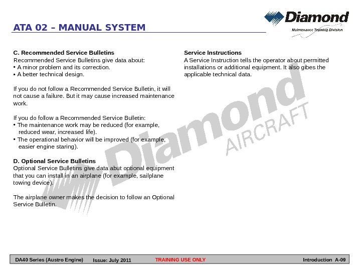
Service Instructions A Service Instruction tells the operator about permitted installations or additional equipment. It also gibes the applicable technical data. ATA 02 – MANUAL SYSTEM TRAINING USE ONLYC. Recommended Service Bulletins give data about: • A minor problem and its correction. • A better technical design. If you do not follow a Recommended Service Bulletin, it will not cause a failure. But it may cause increased maintenance work. If you do follow a Recommended Service Bulletin: • The maintenance work may be reduced (for example, reduced wear, increased life). • The operational behavior will be improved (for example, easier engine staring). D. Optional Service Bulletins give data abut optional equipment that you can install in an airplane (for example, sailplane towing device). The airplane owner makes the decision to follow an Optional Service Bulletin. Introduction A-09 DA 40 Series (Austro Engine) Issue: July
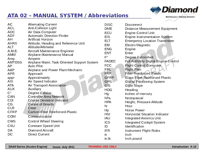
AC Alternating Current ACL Anti-Collision Light ADC Air Data Computer ADF Automatic Direction Finder AH Artificial Horizon AHRS Attitude, Heading and Reference Unit ALT Altitude/Altimeter A. M. E. Aircraft Maintenance Engineer AMM Airplane Maintenance Manual Ampere AMTOSS Airplane Maint. Task Oriented Support System AP Auto Pilot A&P Airplane and Power Plant Mechanic APR Approach appr Approximately ASI Air Speed Indicator ATA Air Transport Association AUX Auxiliary C° Degree Celsius CAN Controller Area Network CDI Course Deviation Indicator CG Centre of Gravity CLR Clear CFRP Carbon-Fiber Reinforced-Plastic COM Communication CWS Control Wheel Steering CSU Constant Speed Unit DA Diamond Aircraft DC Direct Current TRAINING USE ONLYATA 02 – MANUAL SYSTEM / Abbreviations DISC Disconnect DME Distance Measurement Equipment ECU Engine Control Unit EIS Engine Instrumentation System ELT Emergency Location Transmitter EM Electro Magnetic ENG Engine ENT Enter F° Degree Fahrenheit FADEC Full Authority Digital Engine Control FCC Flight Control Computer FPL Flight Plan FRP Fiber Reinforced Plastic GFRP Glass Fiber Reinforced Plastic GPS Global Positioning System G/S Glide Slope HDG Heading Hg inches of mercury h. Pa hectopascal HPA Height, Pressure Altitude hr Hour Hp Horse Power HSI Horizontal Situation Indicator IAU Integrated Avionics Unit ICS Integrated Cockpit System ID Identification IFR Instrument Flight Rules in Inch in. lb Inch pound Introduction A-10 DA 40 Series (Austro Engine) Issue: July
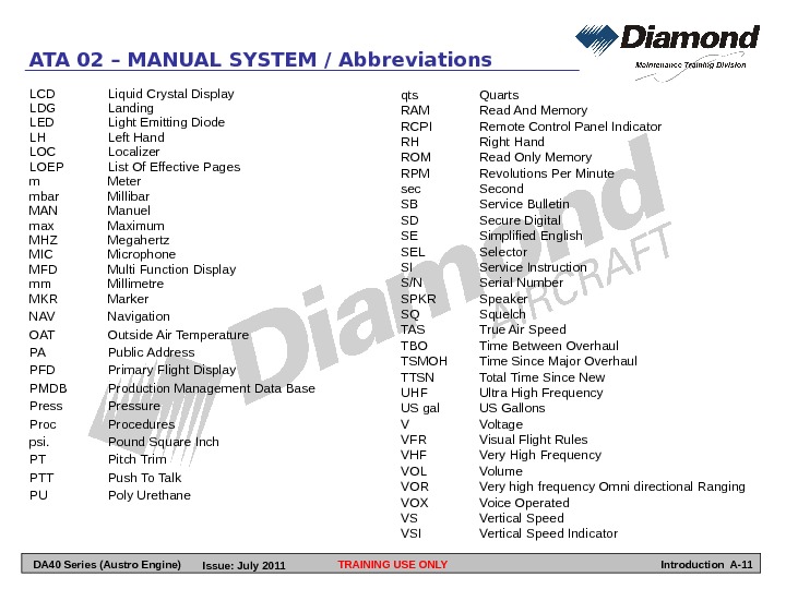
LCD Liquid Crystal Display LDG Landing LED Light Emitting Diode LH Left Hand LOC Localizer LOEP List Of Effective Pages m Meter mbar Millibar MAN Manuel max Maximum MHZ Megahertz MIC Microphone MFD Multi Function Display mm Millimetre MKR Marker NAV Navigation OAT Outside Air Temperature PA Public Address PFD Primary Flight Display PMDB Production Management Data Base Pressure Procedures psi. Pound Square Inch PT Pitch Trim PTT Push To Talk PU Poly Urethane TRAINING USE ONLYATA 02 – MANUAL SYSTEM / Abbreviations qts Quarts RAM Read And Memory RCPI Remote Control Panel Indicator RH Right Hand ROM Read Only Memory RPM Revolutions Per Minute sec Second SB Service Bulletin SD Secure Digital SE Simplified English SEL Selector SI Service Instruction S/N Serial Number SPKR Speaker SQ Squelch TAS True Air Speed TBO Time Between Overhaul TSMOH Time Since Major Overhaul TTSN Total Time Since New UHF Ultra High Frequency US gal US Gallons V Voltage VFR Visual Flight Rules VHF Very High Frequency VOL Volume VOR Very high frequency Omni directional Ranging VOX Voice Operated VS Vertical Speed VSI Vertical Speed Indicator Introduction A-11 DA 40 Series (Austro Engine) Issue: July
TRAINING USE ONLYATA 02 – MANUAL SYSTEM LEFT BLANK Introduction A-12 DA 40 Series (Austro Engine) Issue: July